Christian Torres
Mechanical Engineer
About Me
My name is Christian Torres and I graduated from the University of Texas at Austin with a bachelor's degree in mechanical engineering. I am currently working in the semiconductor industry as a manufacturing engineer. I created this website in 2023 to showcase some of the work I've done individually and during my time at UT Austin.
About This Website
This is my third attempt in "creating" a website. For my first attempt, I utilized the third party software, Wix. Although usable, it didn't really suit the needs I was looking for. So, for my second attempt, I coded a website from scratch. While functional, the resulting site looked dated. On my third attempt, I made use of a template to help create this site.
SolidWorks
-
-
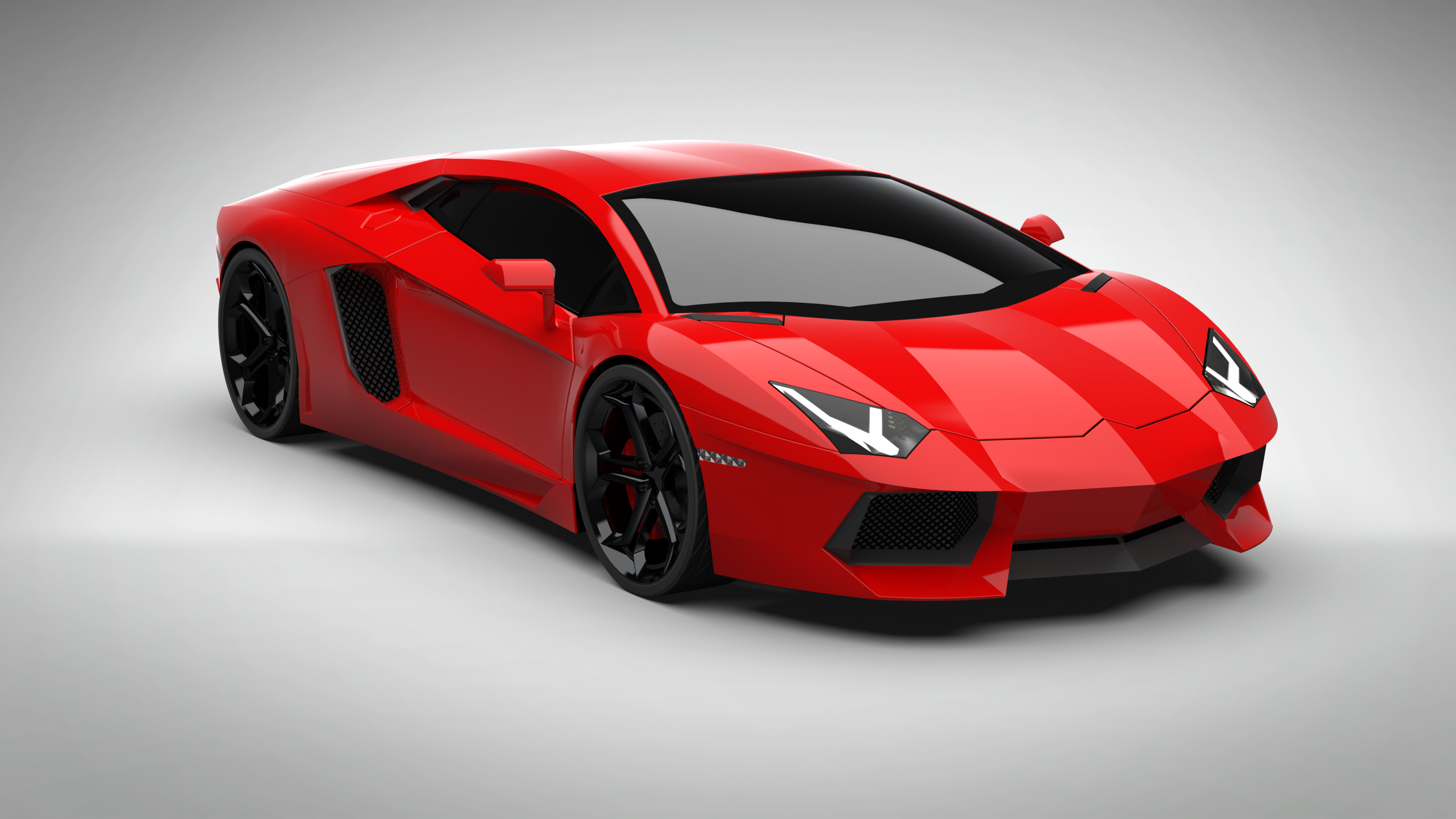
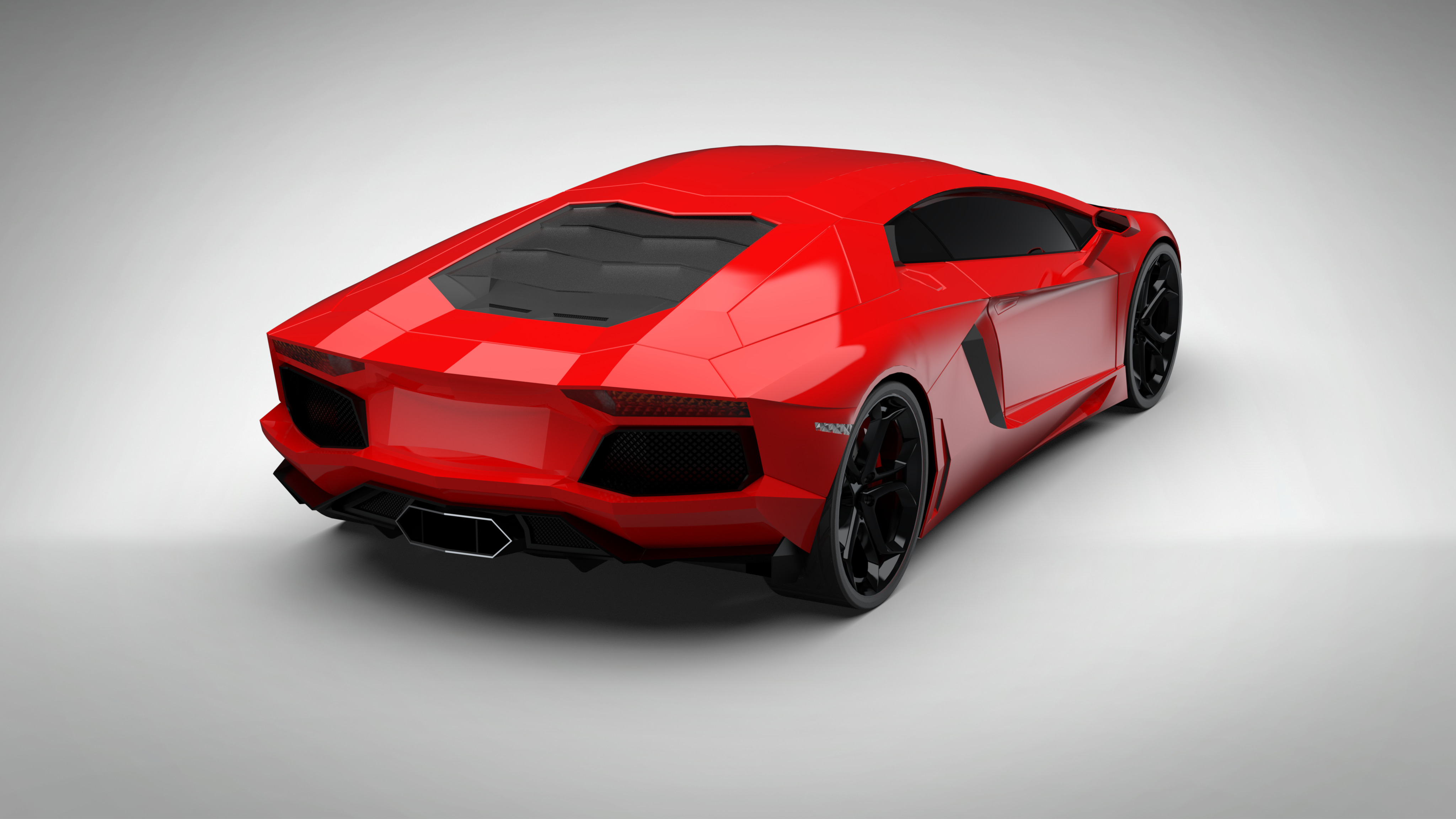
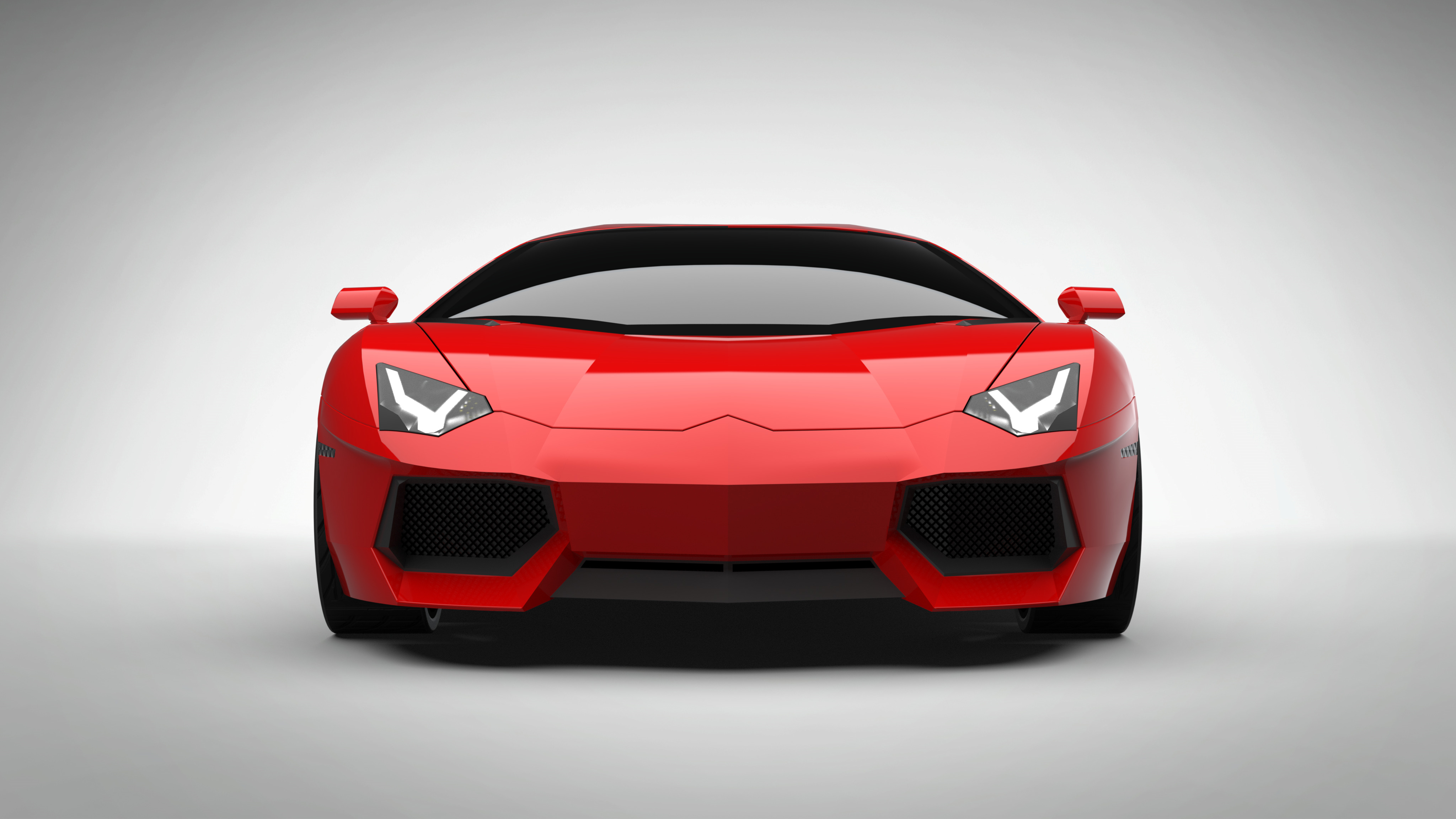
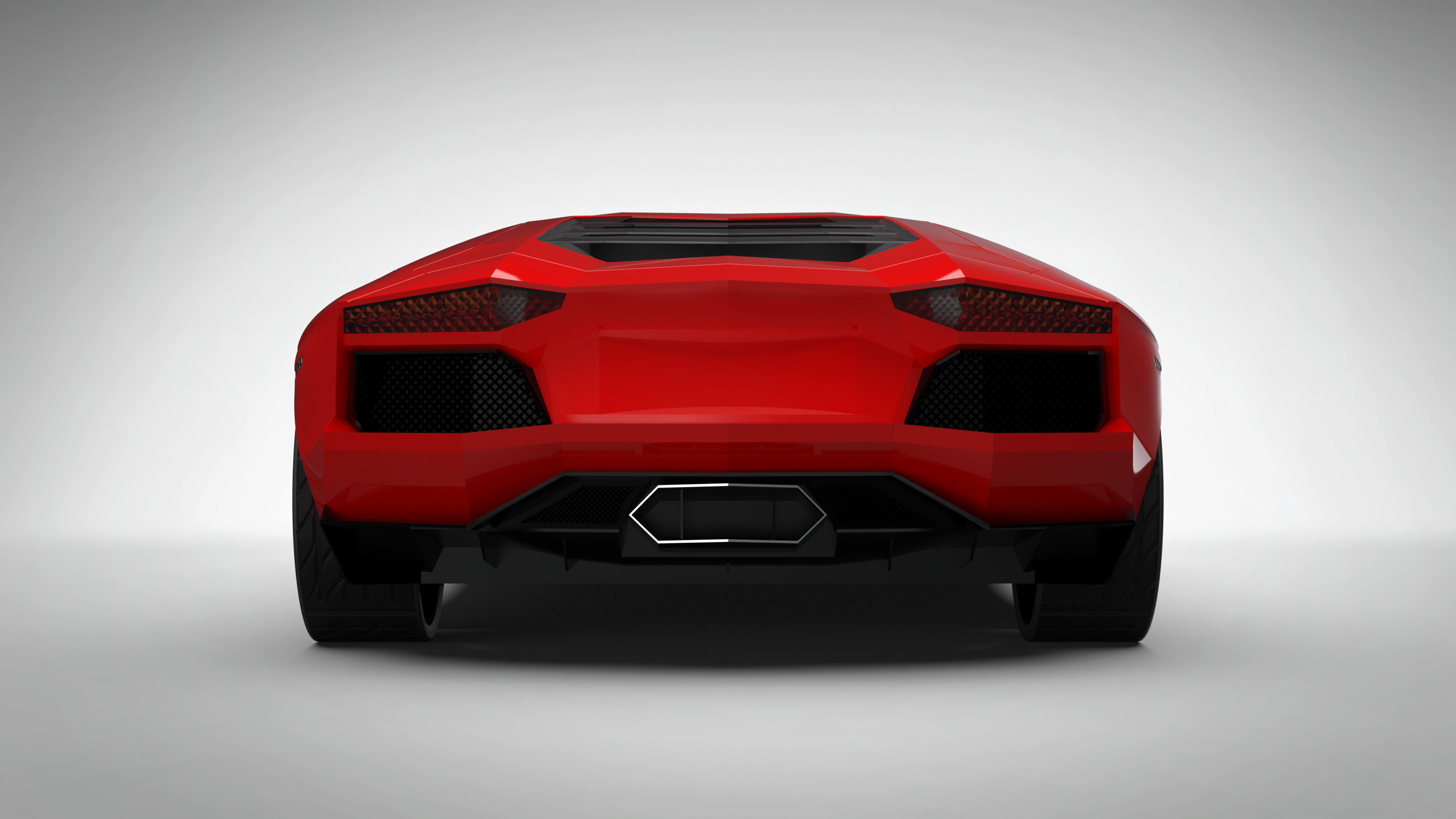
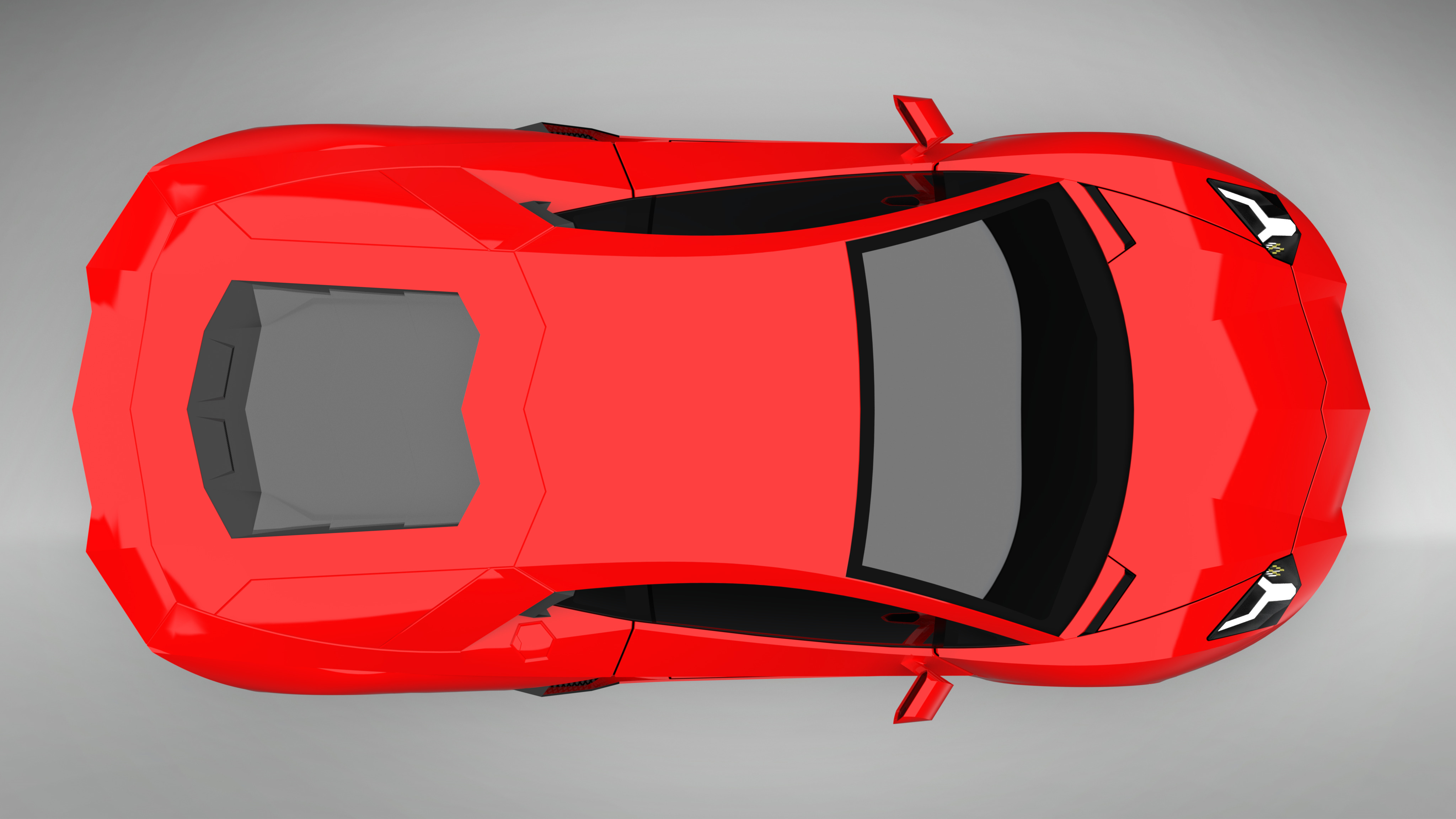
This was my second attempt at the Lamborghini Aventador I made back in February. This time around, I had a lot more experience under my belt which resulted in a model which I am very happy with.
Technical: This time around, the model was created from 4 reference pictures which allowed for more accurate geometry and size ratios. The body was mainly constructed with filled, boundary, swept, and ruled surfaces. One of the main differences this time around was the heavy use of projected curves which allowed for smoother/more controlled 3D curves. The final model body consisted of about 600 individual surfaces.

-
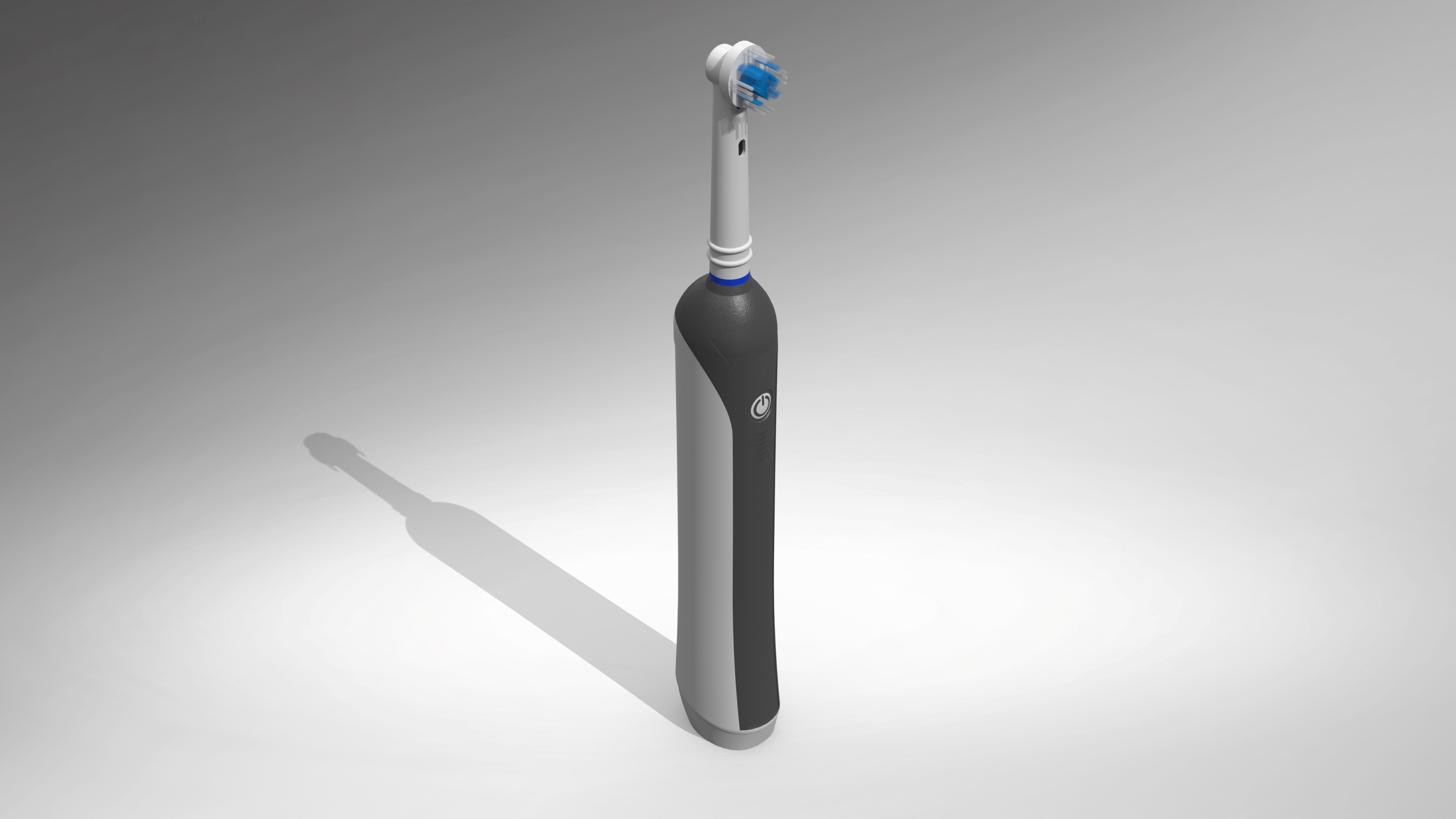
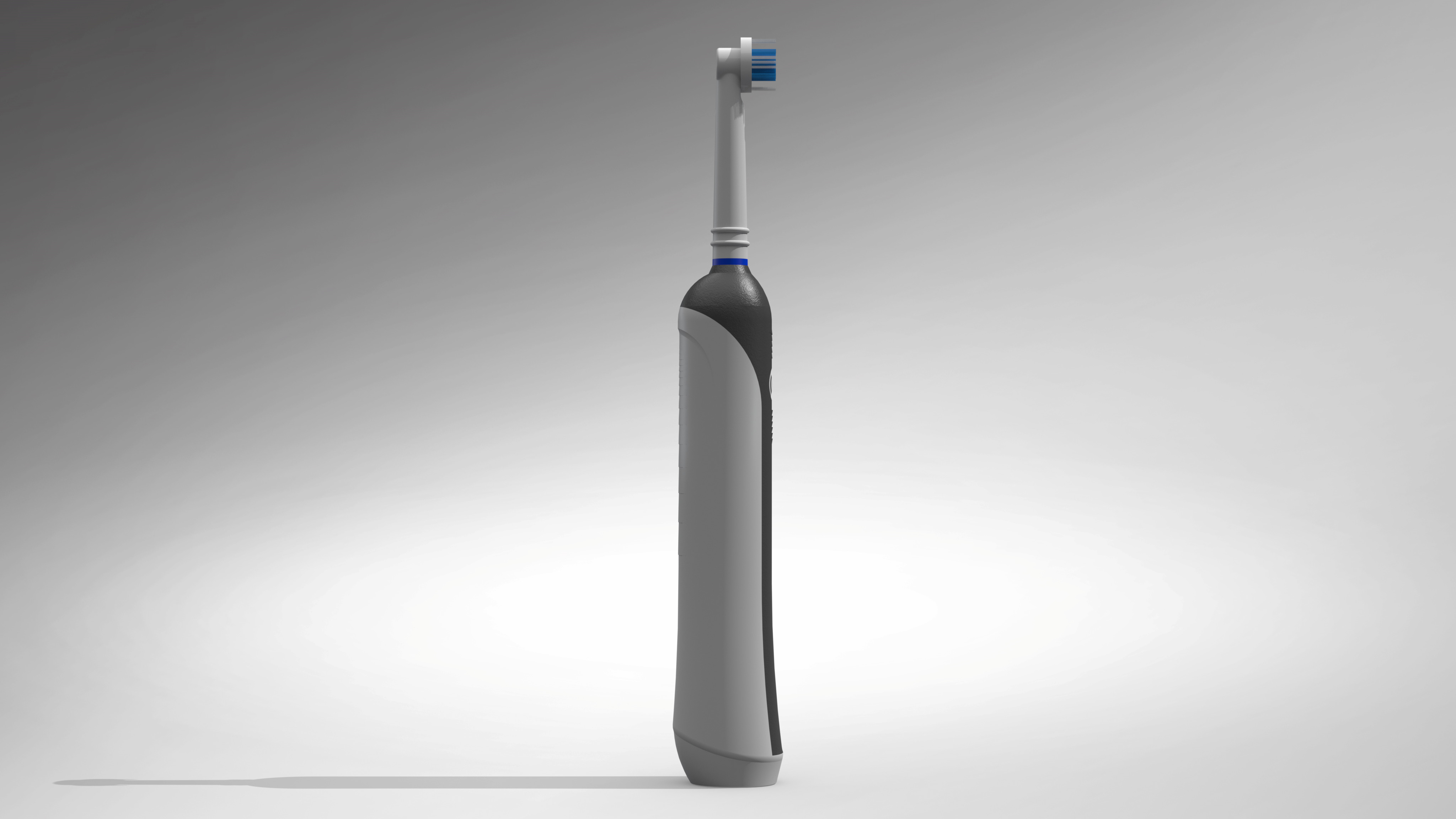
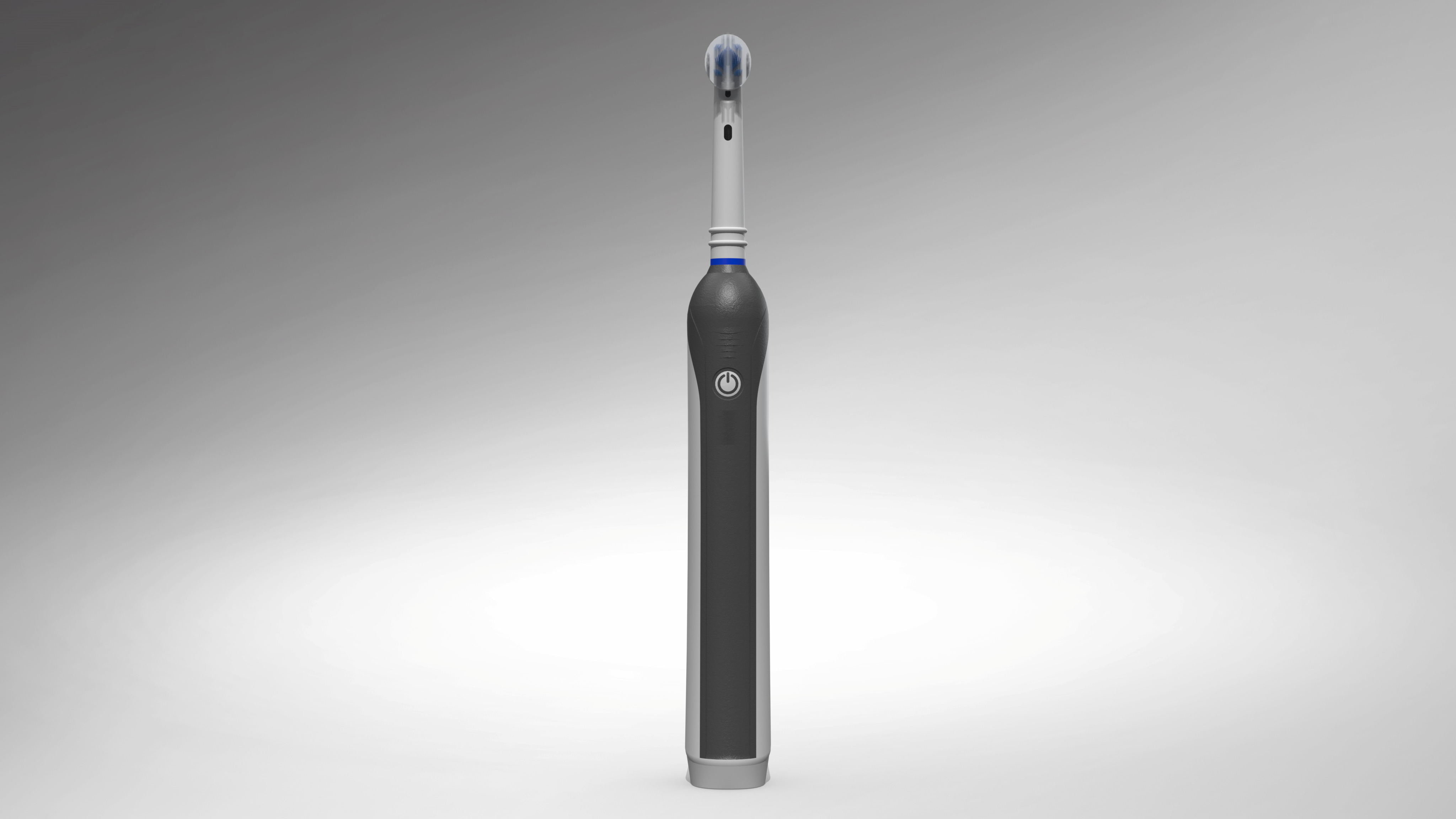
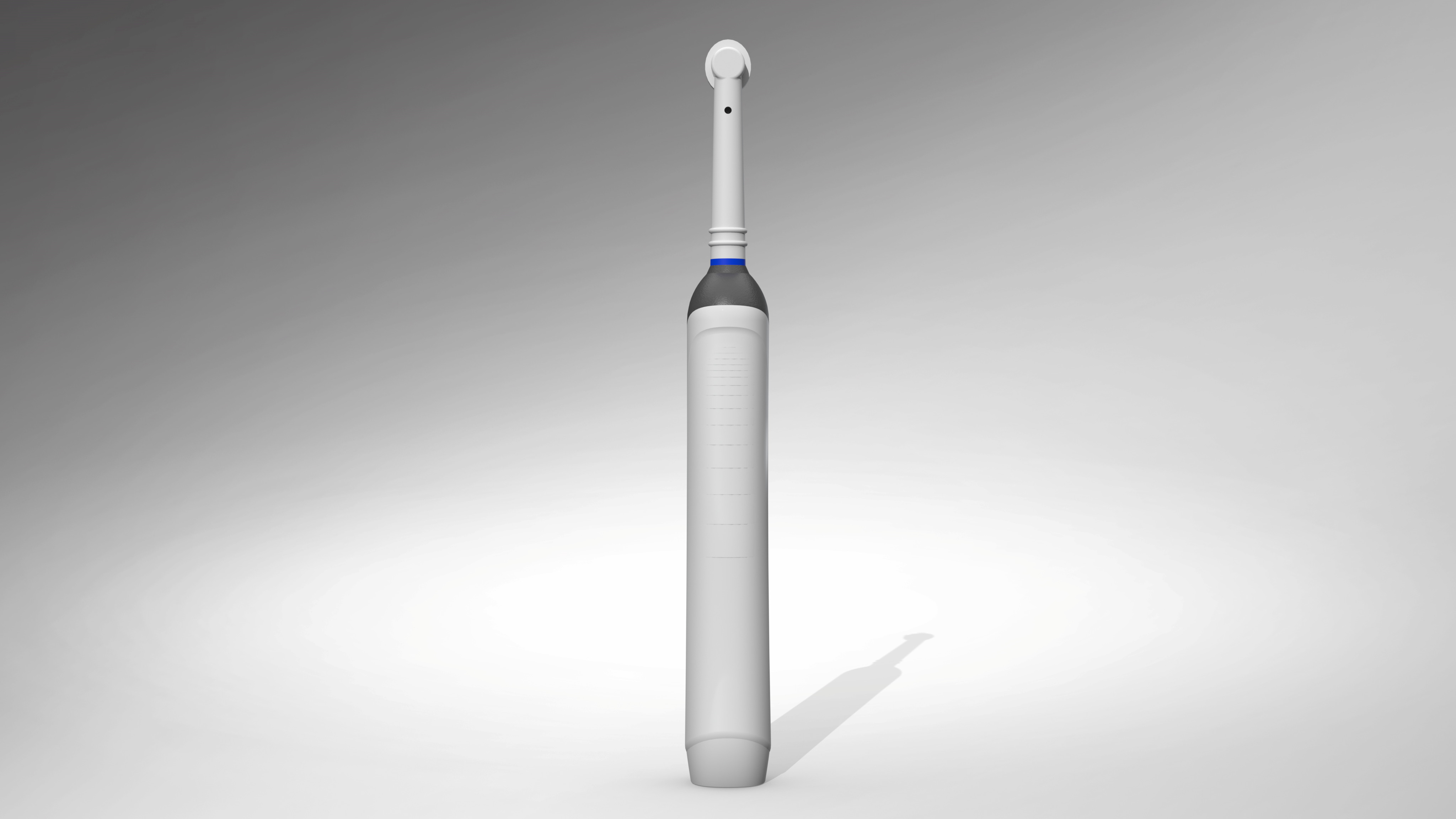
Like some of the other models I’ve made, I made this model to help build experience with SolidWorks.
Technical: The model was created through surface modeling. Since the model was not overly complex, dial caliper measurements were used rather than reference pictures. The hardest portions to model came from the smaller details. Of these small details, the “grips” that stick out of the material were the trickiest.
-
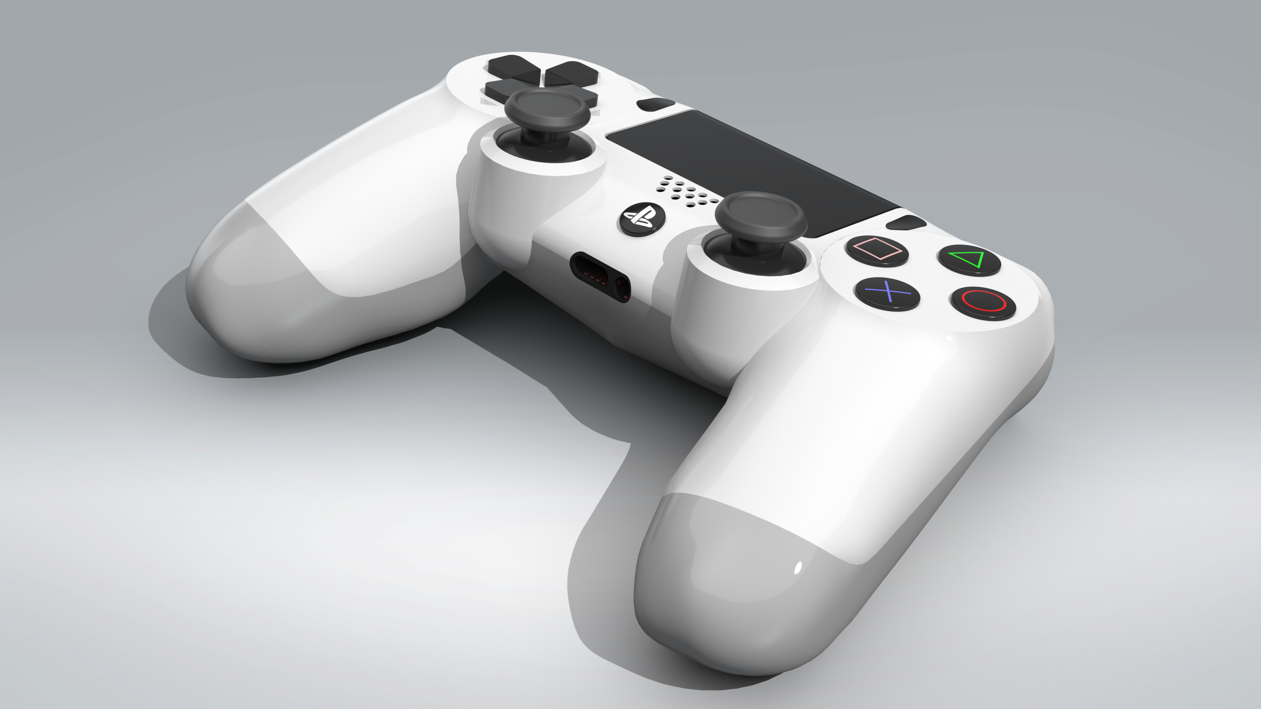
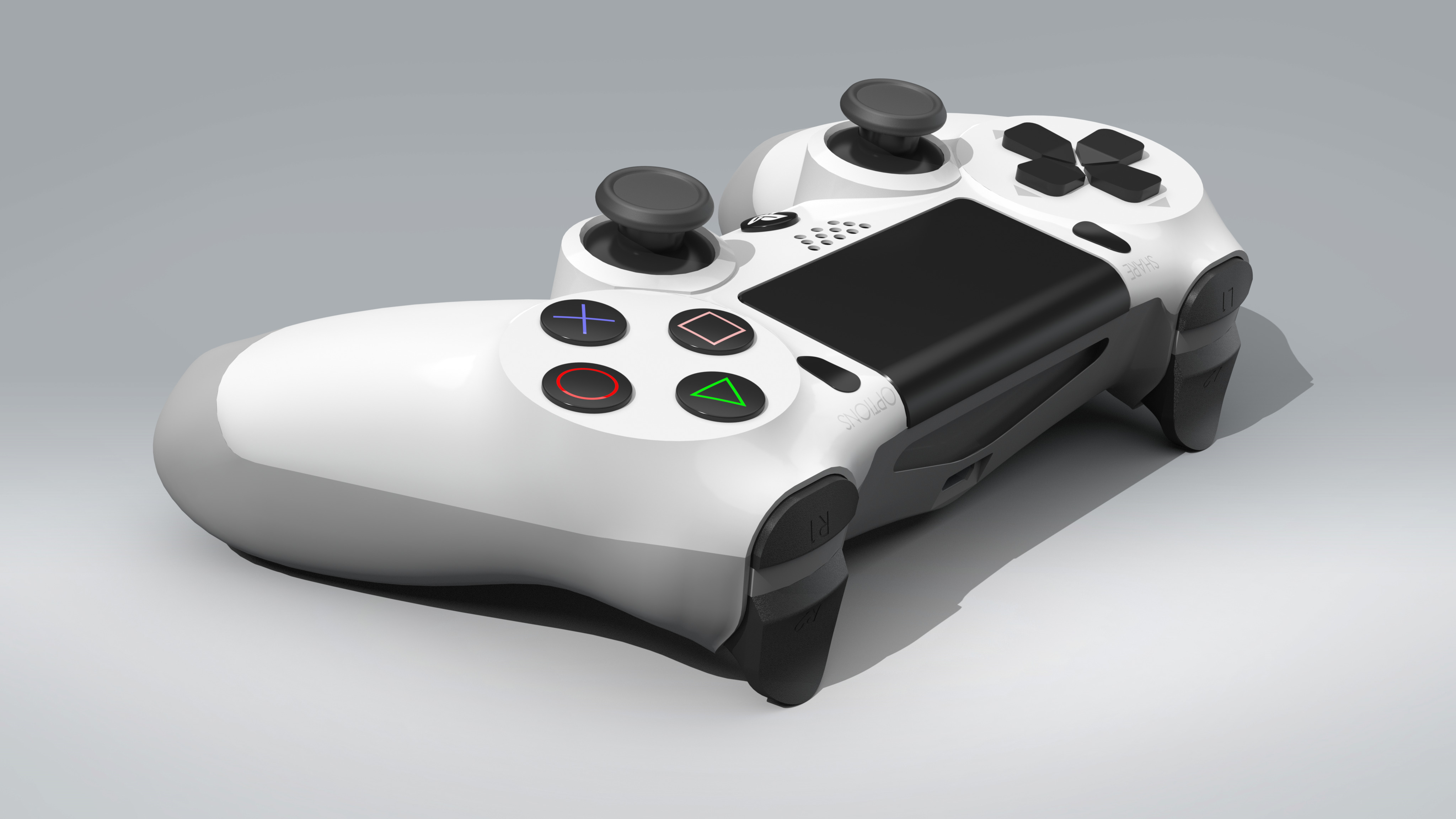
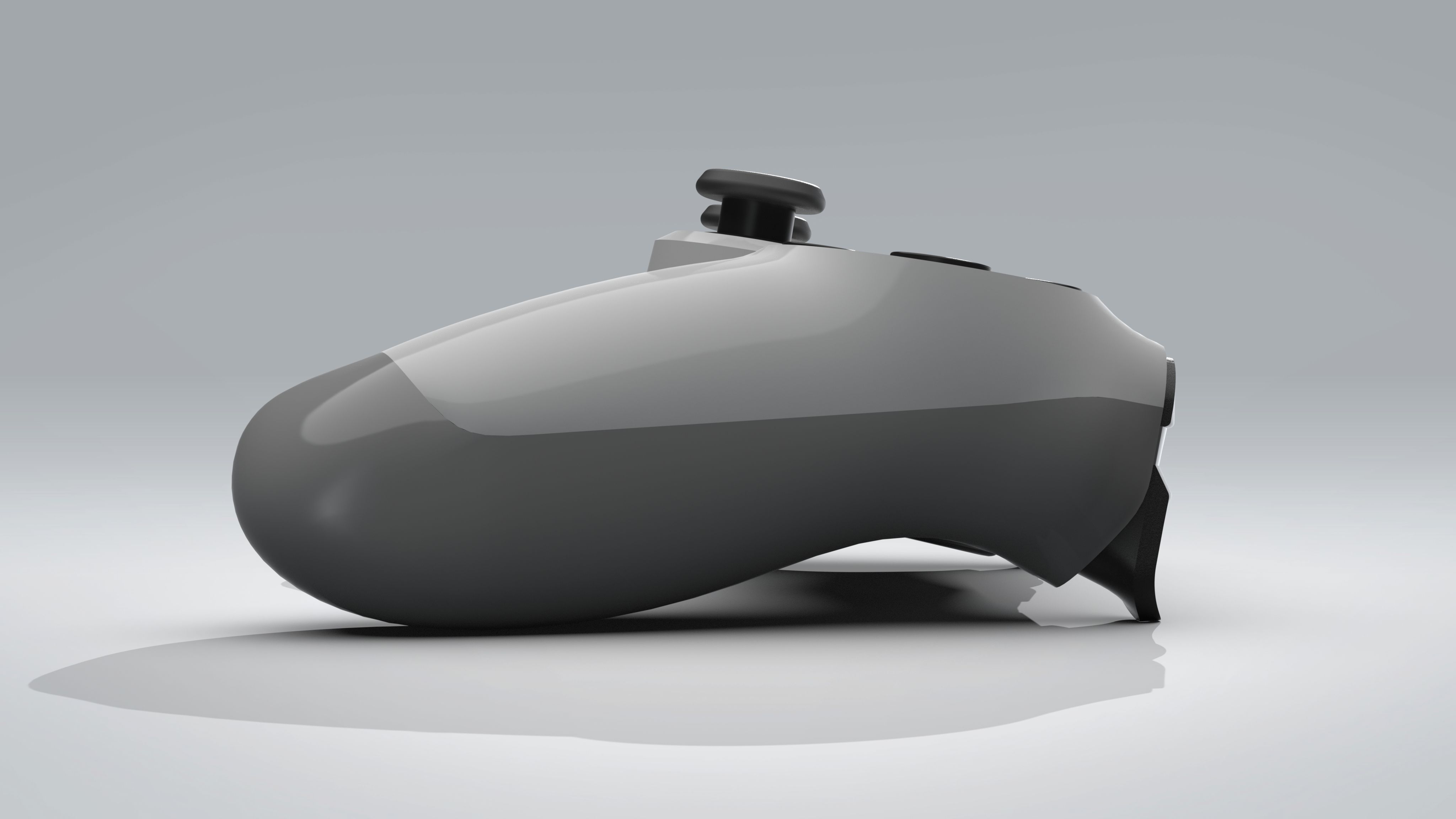
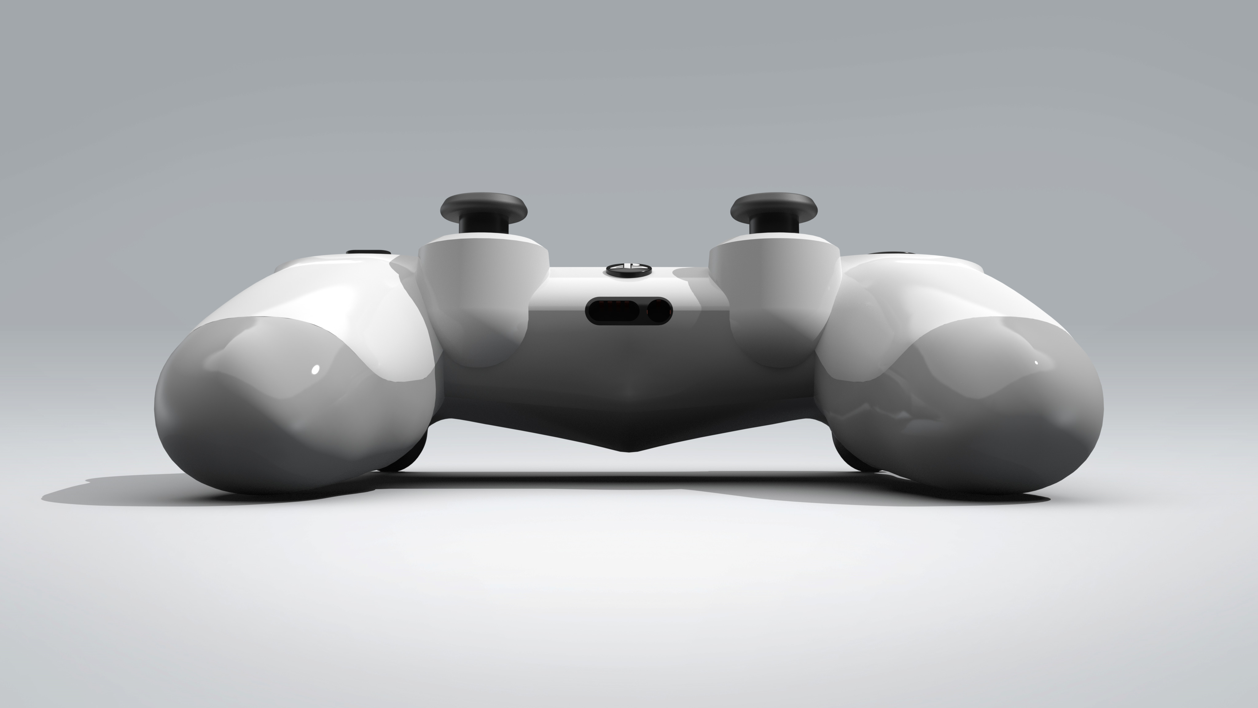
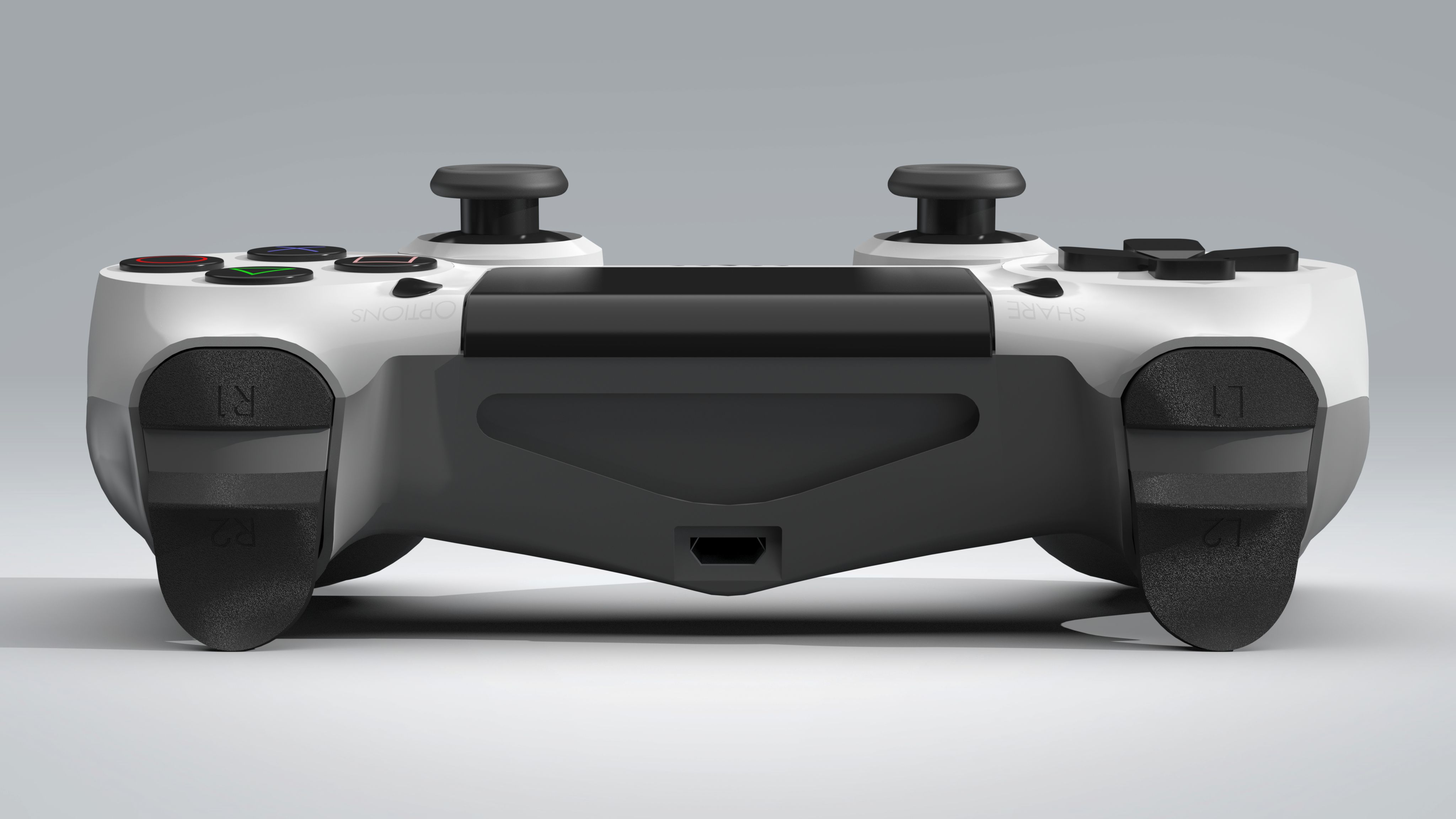
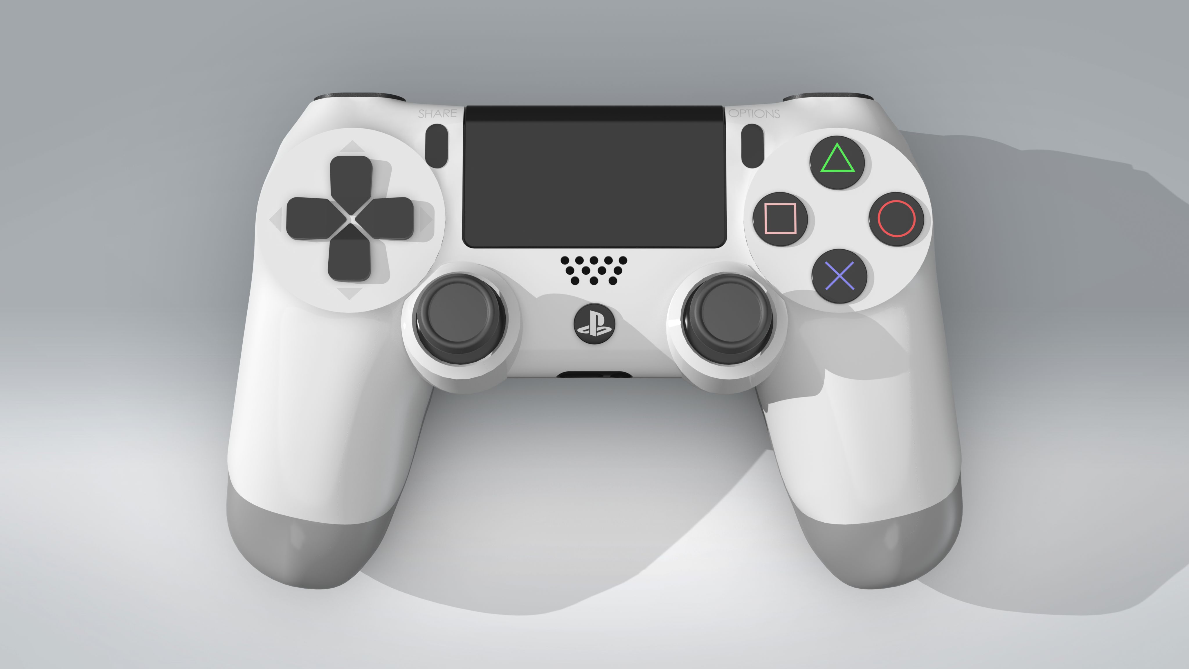
The PS4 controller is tied for most complex model I've done so far. I've been meaning to model this object for quite some time, but have lacked the skill to do so. Overall, the model turned out ok as of now. My main issue with the model is the gray portion of the controller is not as smooth as it should be. I will revisit this portion in the future.
Technical: The main portions of the controller, the white and gray pieces, were built through the use of surfaces (mainly boundary and filled surfaces). The primary focus was to achieve curviture continious surfaces. This was achieved for the white surface. The rest of the components were all relatively straightforward to build.
-
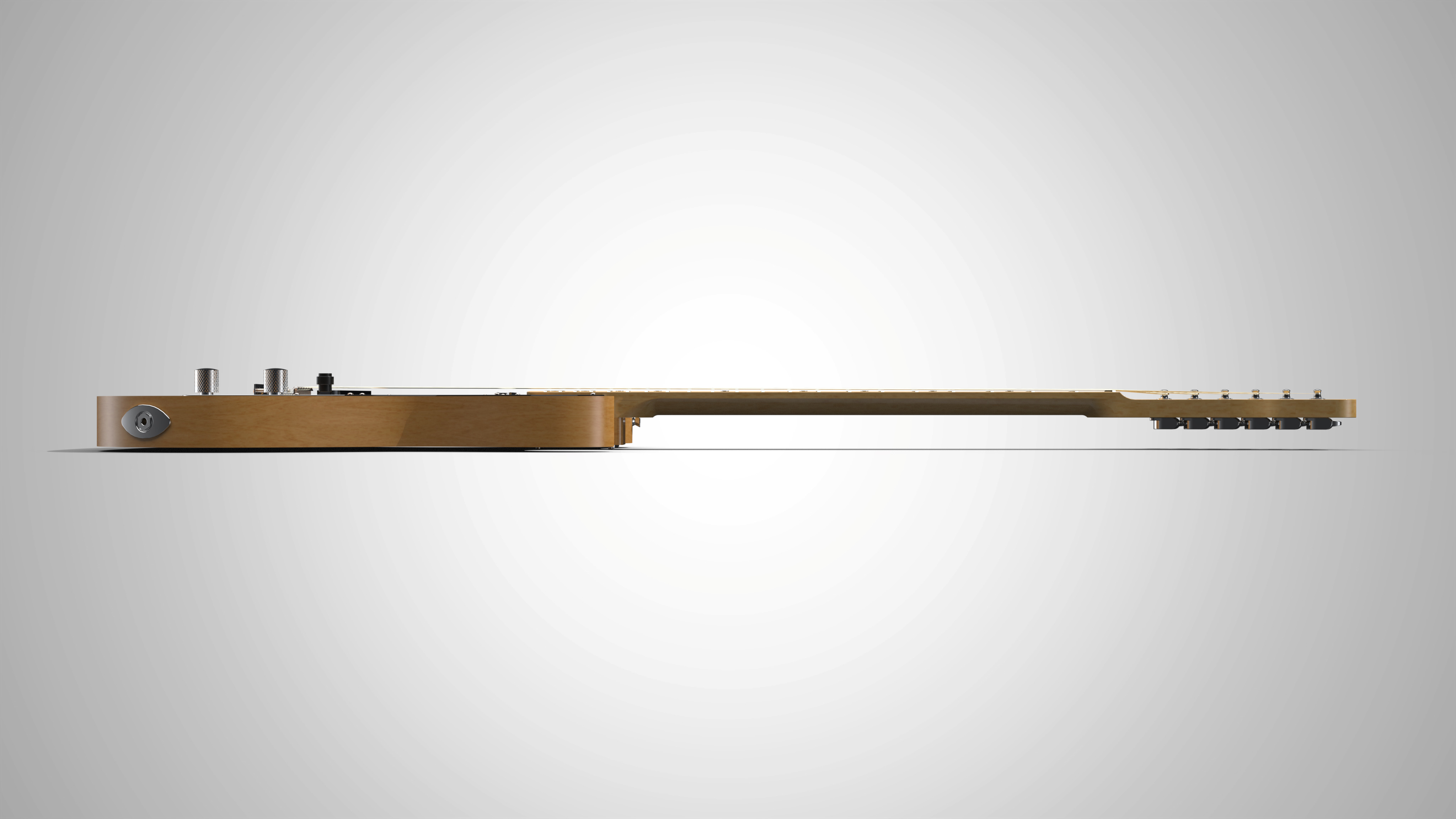
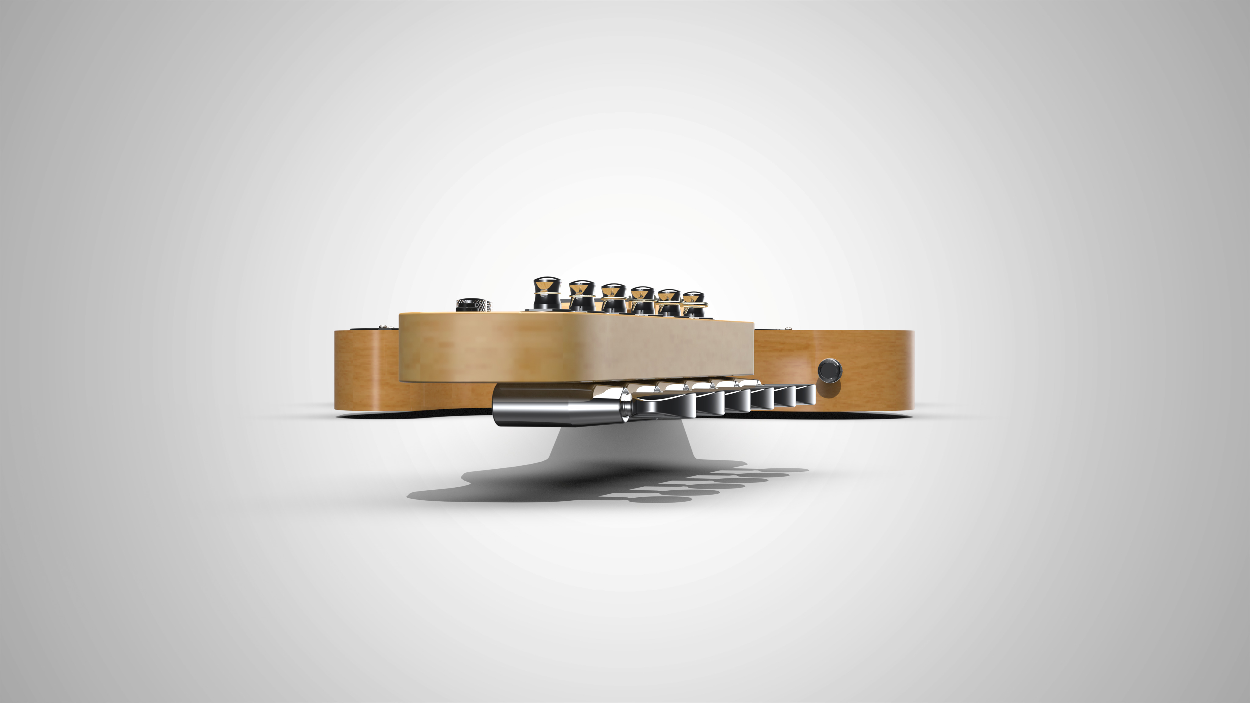
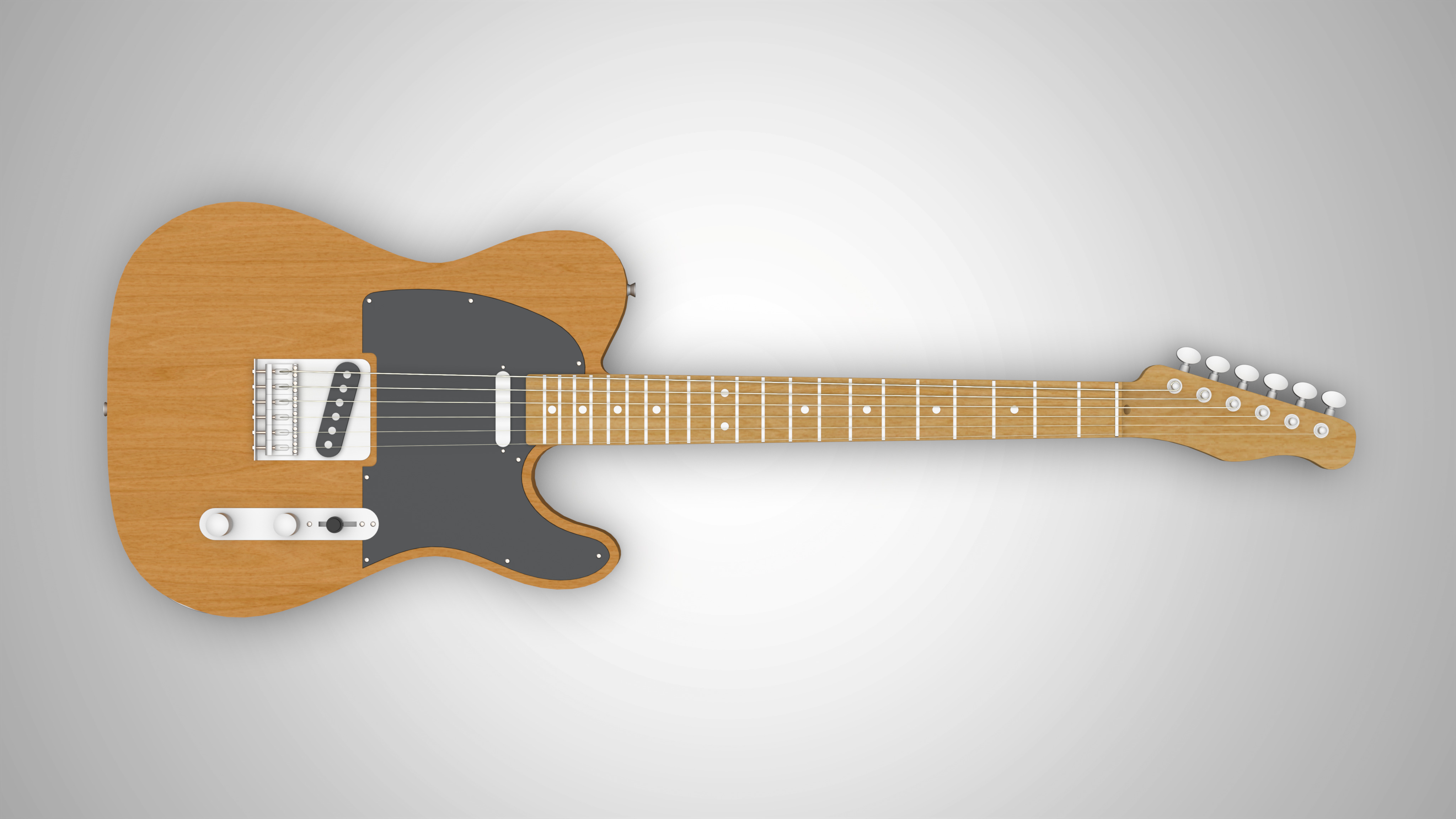
The telecaster model was created for fun and simply to build some more experience.
Technical: The model consisted of two main components: the body and the neck. The body was relatively straightforward to create through the use of the sketch picture command and spline tools. The neck was more difficult to create. A combination of the sweep command and surfacing created most of the neck. The head of the neck was also made through the sketch picture command and spline tools.

-
In this FEA analysis, the power dissipation by convection of various fin configurations was examined. The reason for performing this analysis was to compare the results of SolidWorks’ analysis to that of the analytical solution for one of the configurations. In addition, through this analysis, the relationship between the length and width of the fins to the power dissipated could be illustrated. The image below showcases the heat sink
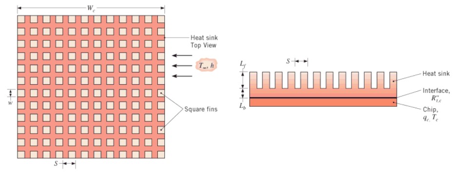
The simulation was ran for the following fin widths and lengths: W = 0.25mm and L = 6mm; W = 0.35mm and L = 6mm; W = 0.45mm and L = 6mm; W = 0.25mm and L = 10mm. The power dissipated for these cases were 8.39W, 11.98W, 15.08W, and 8.98W respectively.
Analysing the results, as expected, the greater the find width the greater the power dissipated. This is due to the increased surface area allowing for increased convection. Increasing the length of the fin seems to have minimum impact. Comparing Solidworks' result to that of the analytical solution for the W = 0.25mm and L = 6mm case (8.52W), there was difference of about 1.5%.
-
In this FEA analysis, the deflection of a beam was measured at two points (A and B). The reason for performing this analysis was to compare the results of SolidWorks’ analysis to that of the analytical solution. The image below showcases the beam:
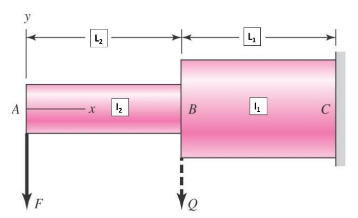
The simulation was ran for the following 3 cases: I2 = 2I1, I2 = 4I1, L2 = 3L1.
As for how they compared, the deflection in SolidWorks was relatively close to that of the analytical solution for all of the cases. The FEA tool in SolidWorks does a good job in simulating beam deflection and would be very useful when analyzing more complex systems.
-
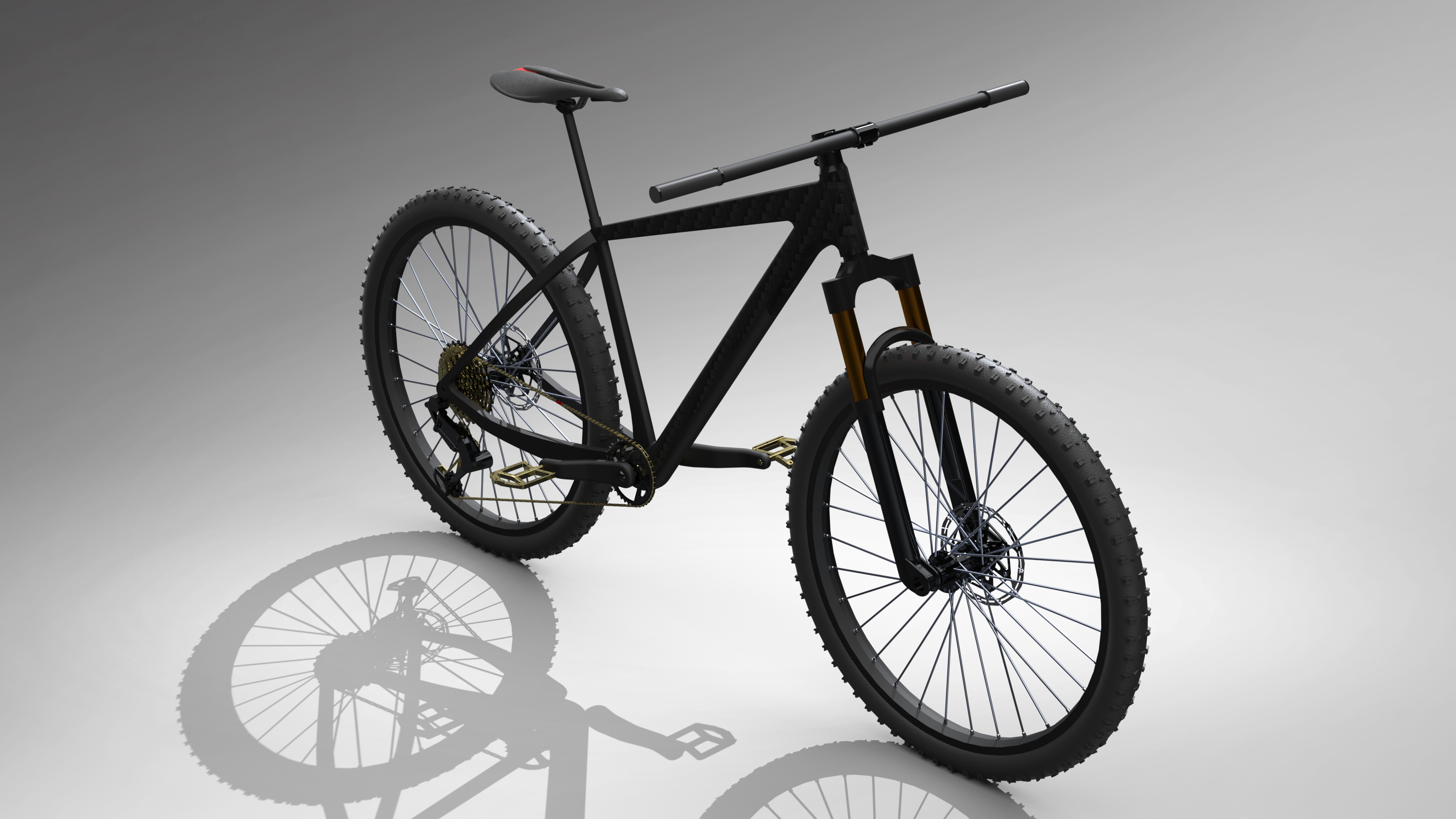
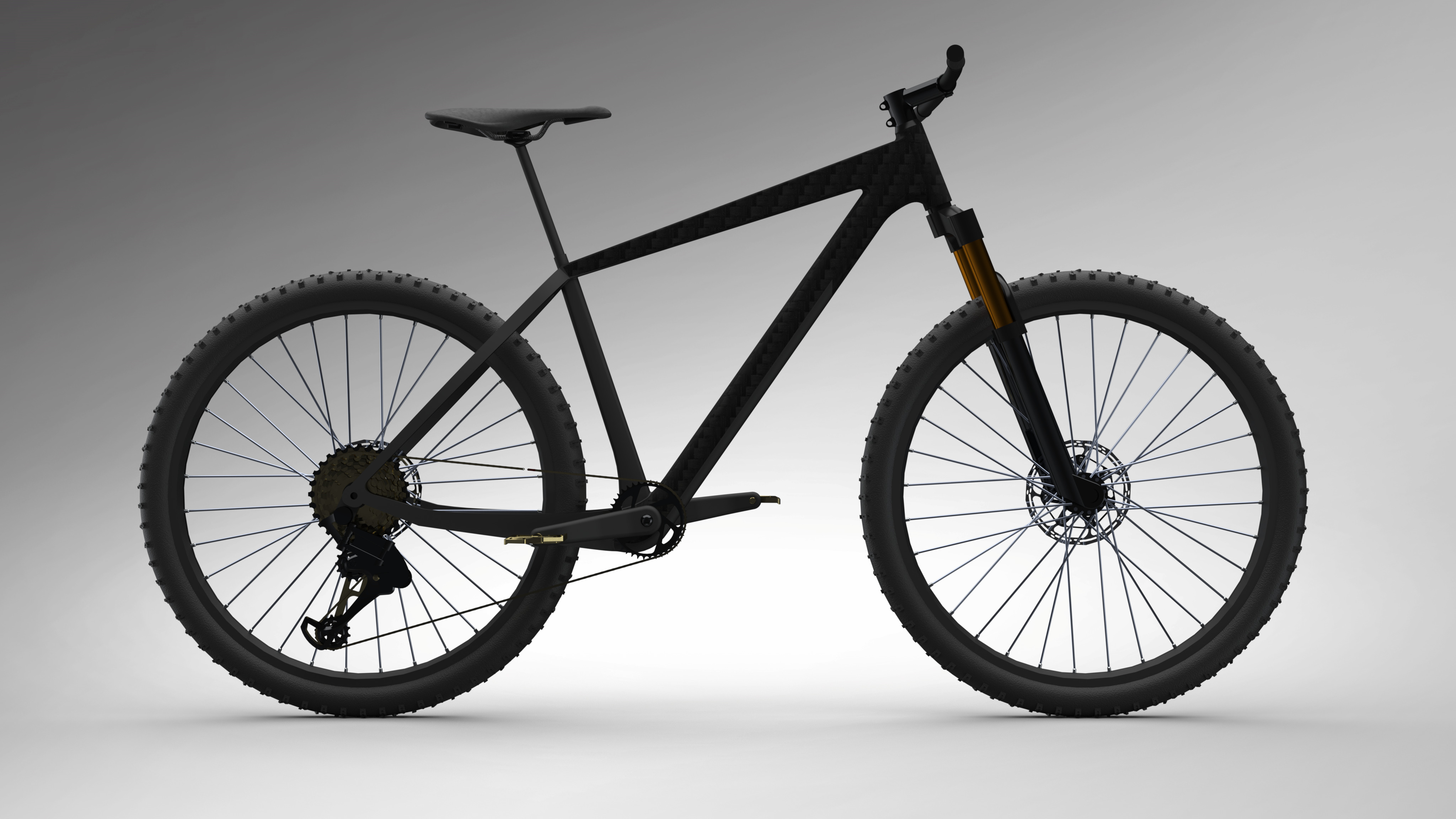
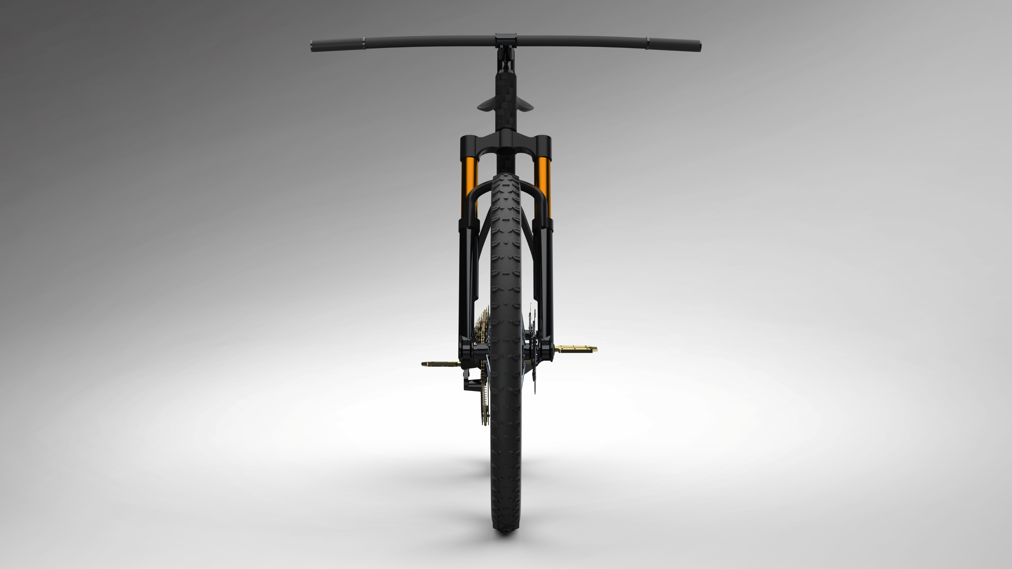
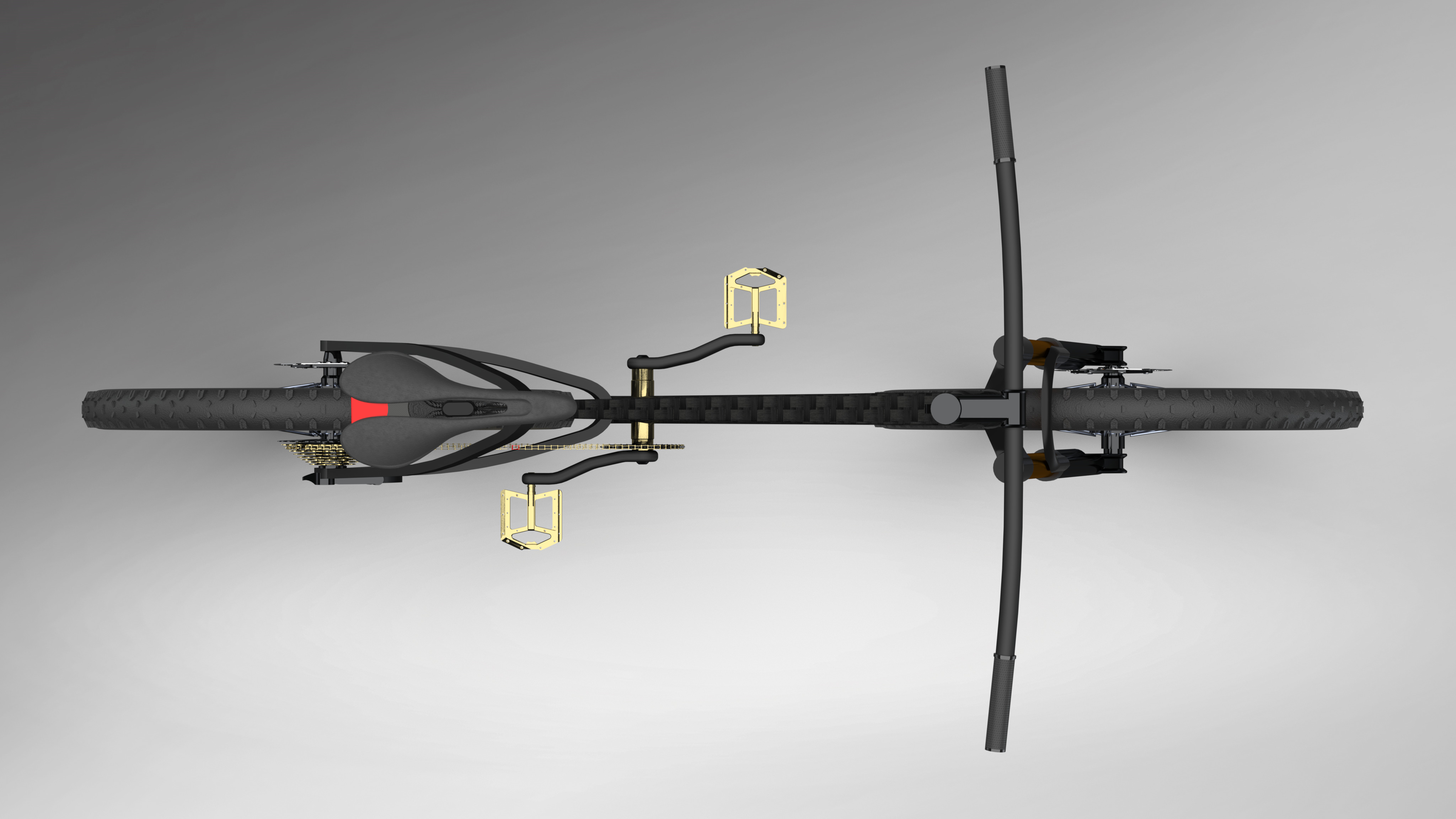
Before starting this model, I wanted to gain experience in creating a functional assembly. To do so, I settled on modeling a bicycle as it contains parts acting together to generate movement. The specific bicycle model I chose was the Cube Elite… bike as I thought it looked sleek and had a very well done 3D model I could reference. I was quite satisfied with the end result. As seen in the video below, the assembly mirrors the motion of an actual bicycle (i.e. pedals turning causes wheels to move).
Technical: Overall, a lot of the components were relatively straightforward to create, albeit time consuming due to the geometry/patterning. The most time consuming part to create in the assembly was the seat which involved surface modeling. The bike chain was created using the chain component pattern. However, as the length of the chain path was not perfectly calibrated to the individual link size, there is a missing link in the chain. The empty space can be seen next to the individual chain colored in red.
-
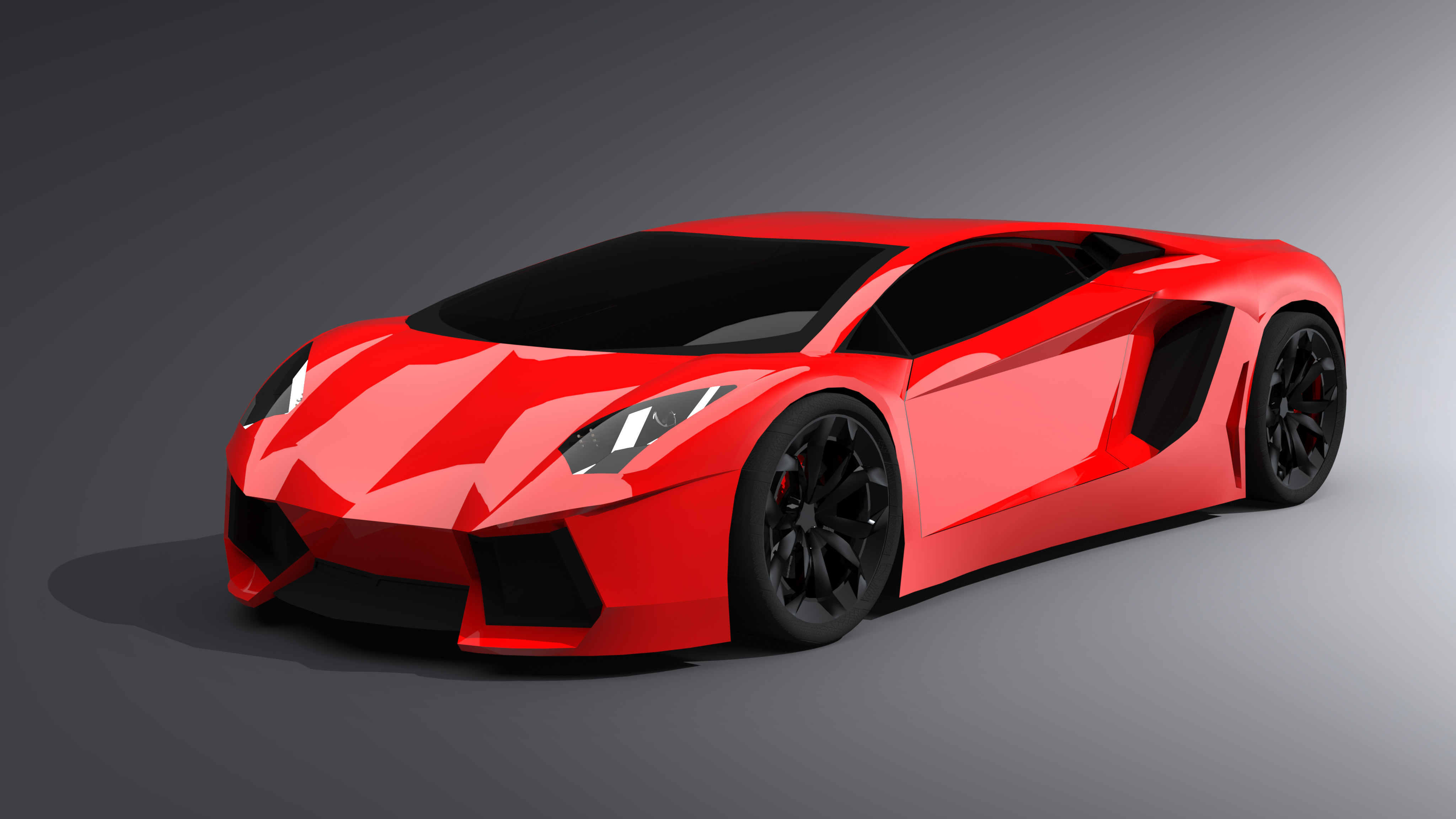
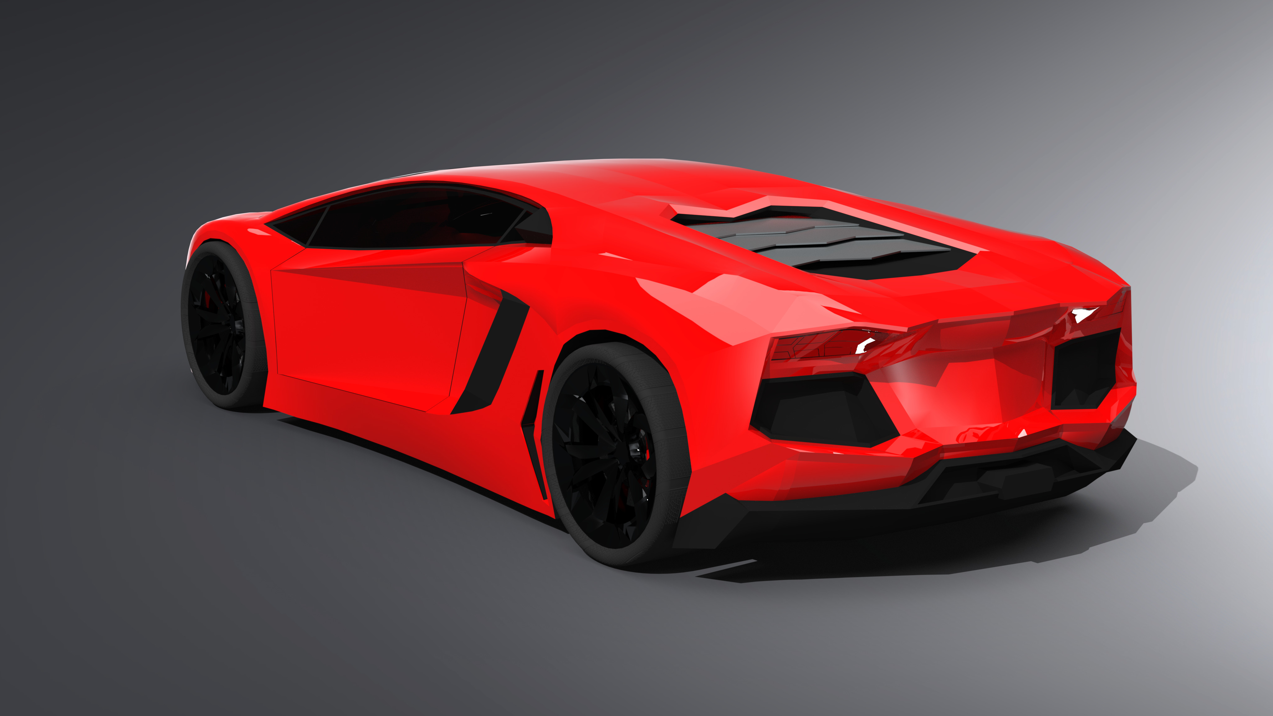
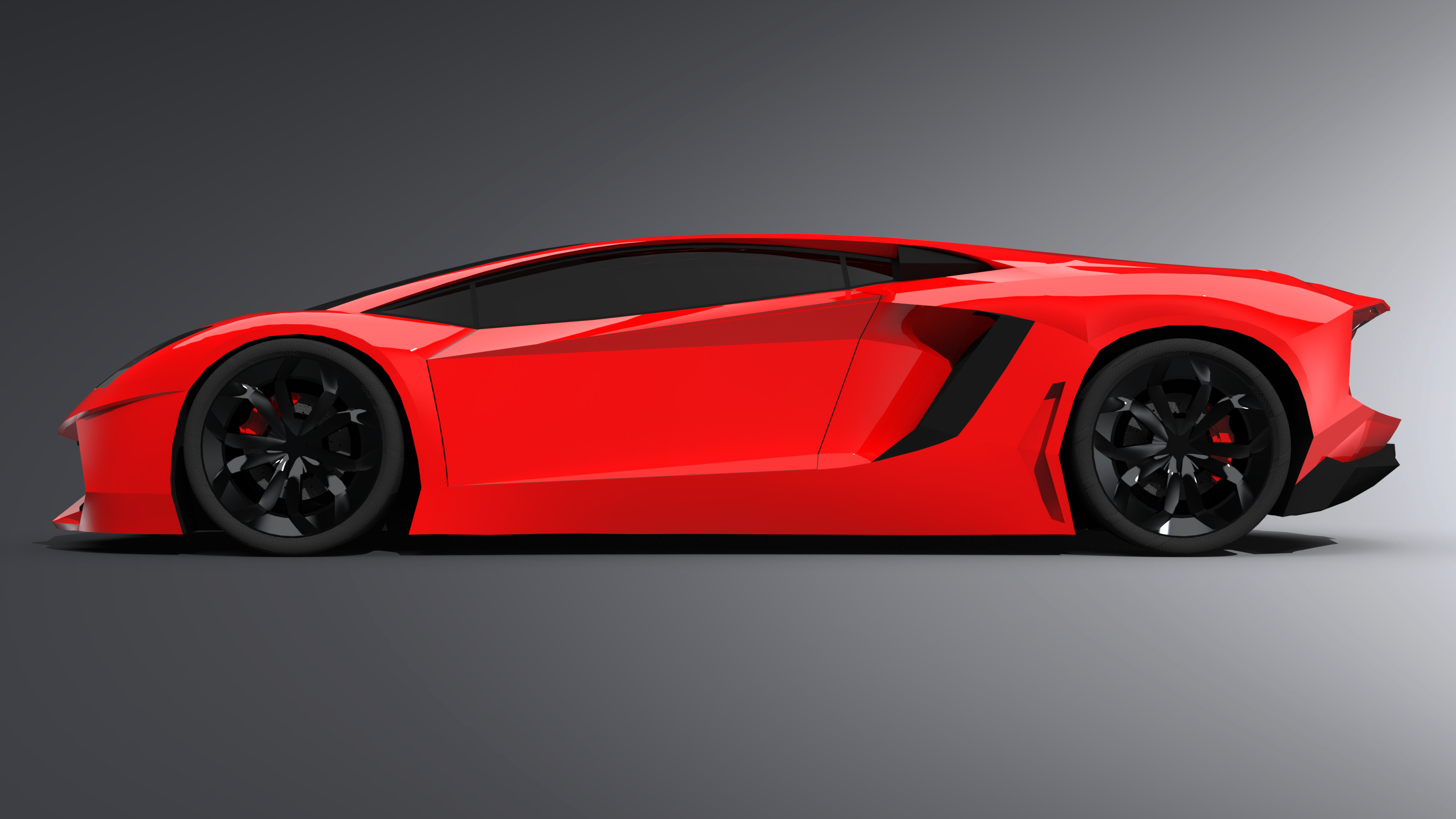
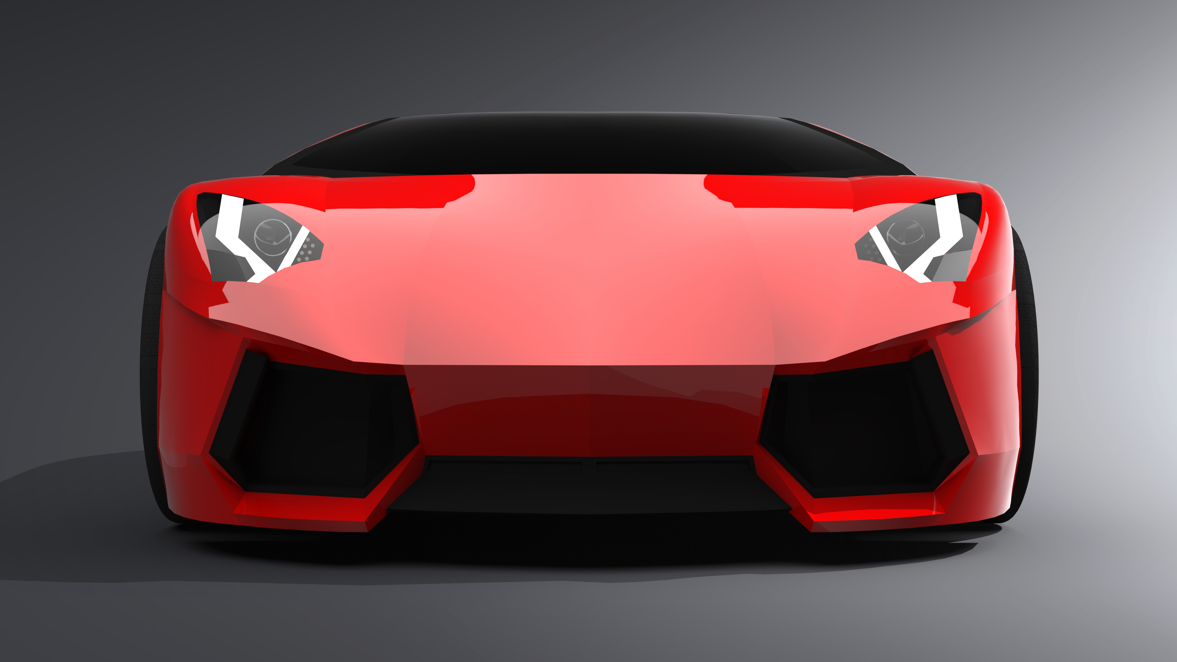
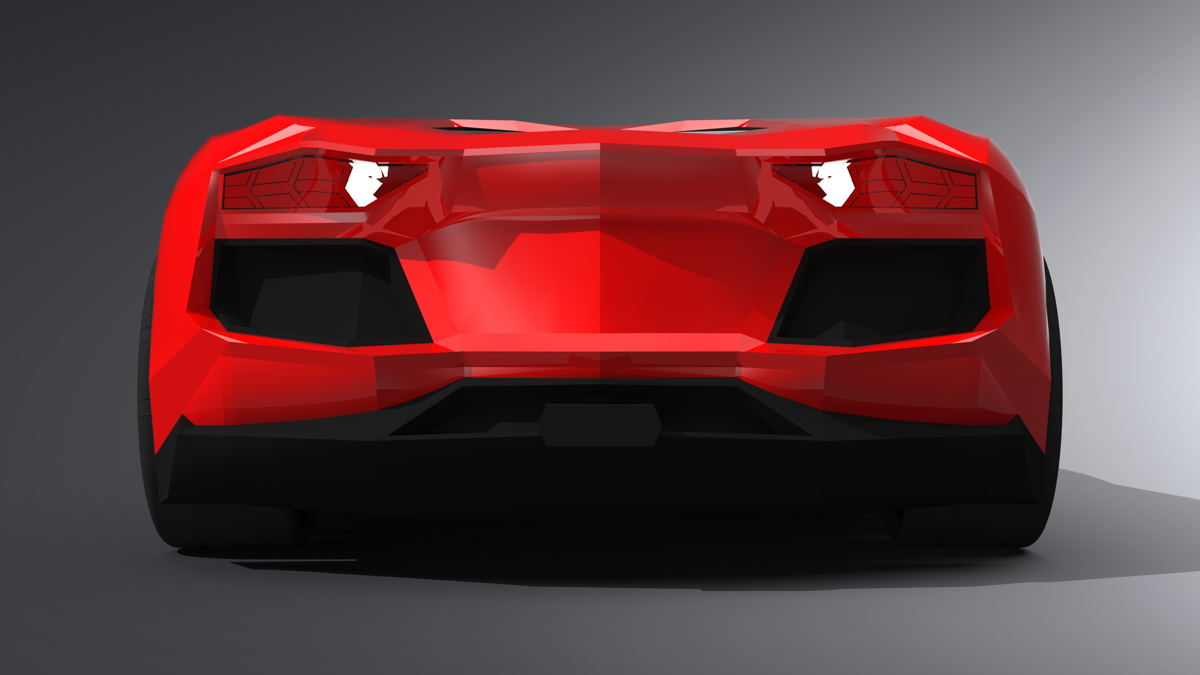
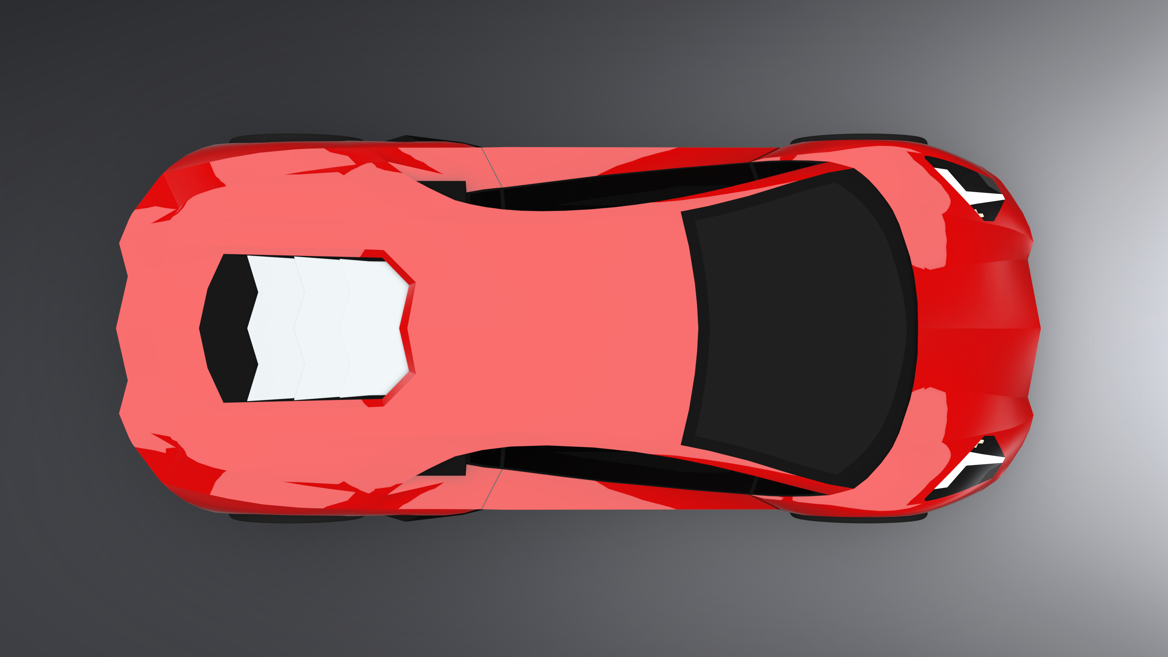
The Aventador is the most time consuming model I’ve made so far. This project heavily utilized the surfacing techniques I’ve learned from previous models. This specific model was chosen for the following reasons: it contained complex geometry to try and model as well as looking cool. Overall, I am satisfied with how the model turned out. In the future, as my ability improves, I hope to correct and smoothen some of the geometry and body ratios.
Technical: The model was created from 2 main reference pictures: top view and side view pictures. Utilizing these reference pictures, 3D splines were utilized to create the side body. As for the front and rear portions, as well as geometry that lied into the model (e.g. how the doors curve in), those were “eyeballed” based on “what looks right”. The majority of the individual surfaces were boundary surfaces and a few were filled.
-
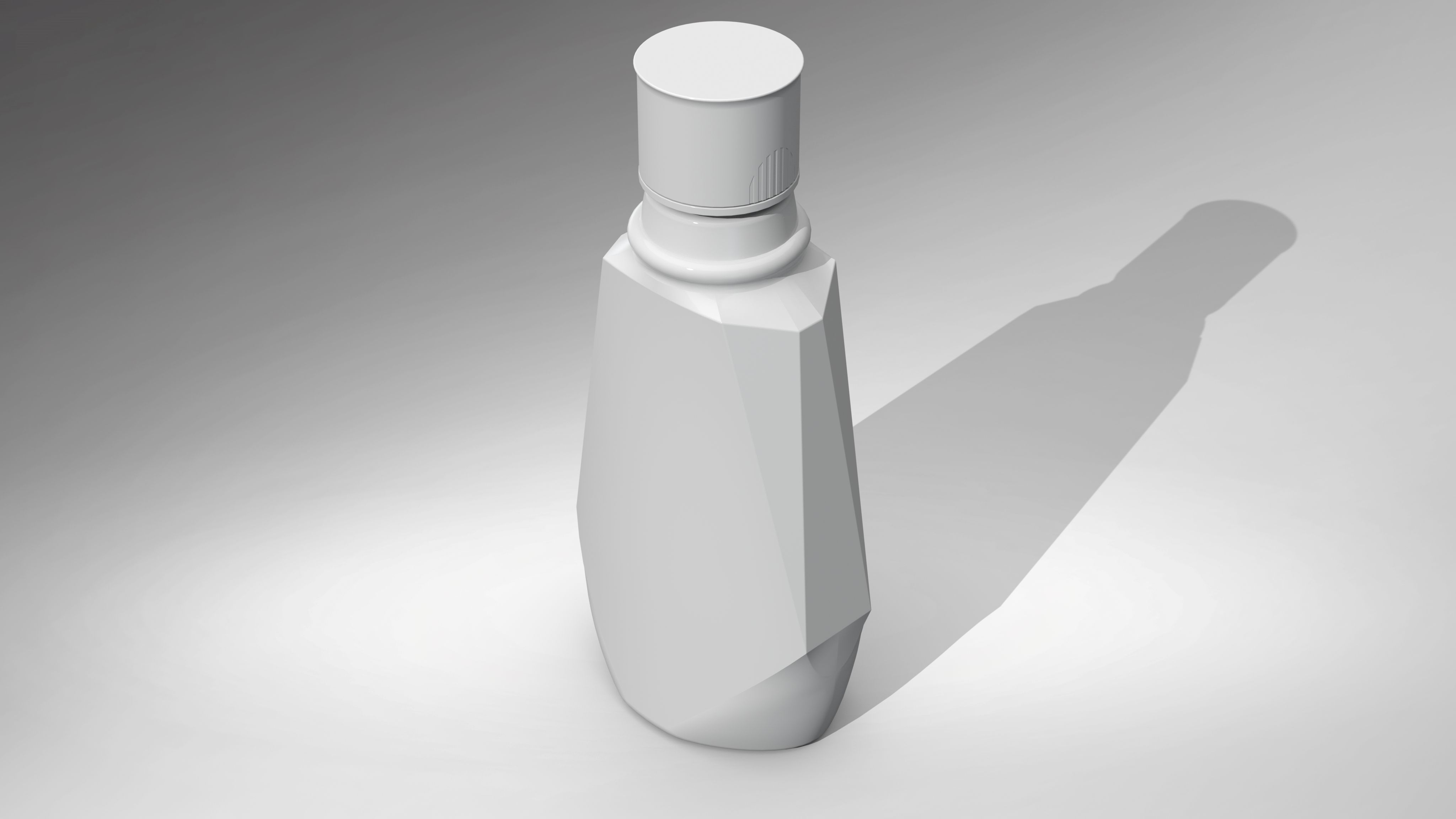
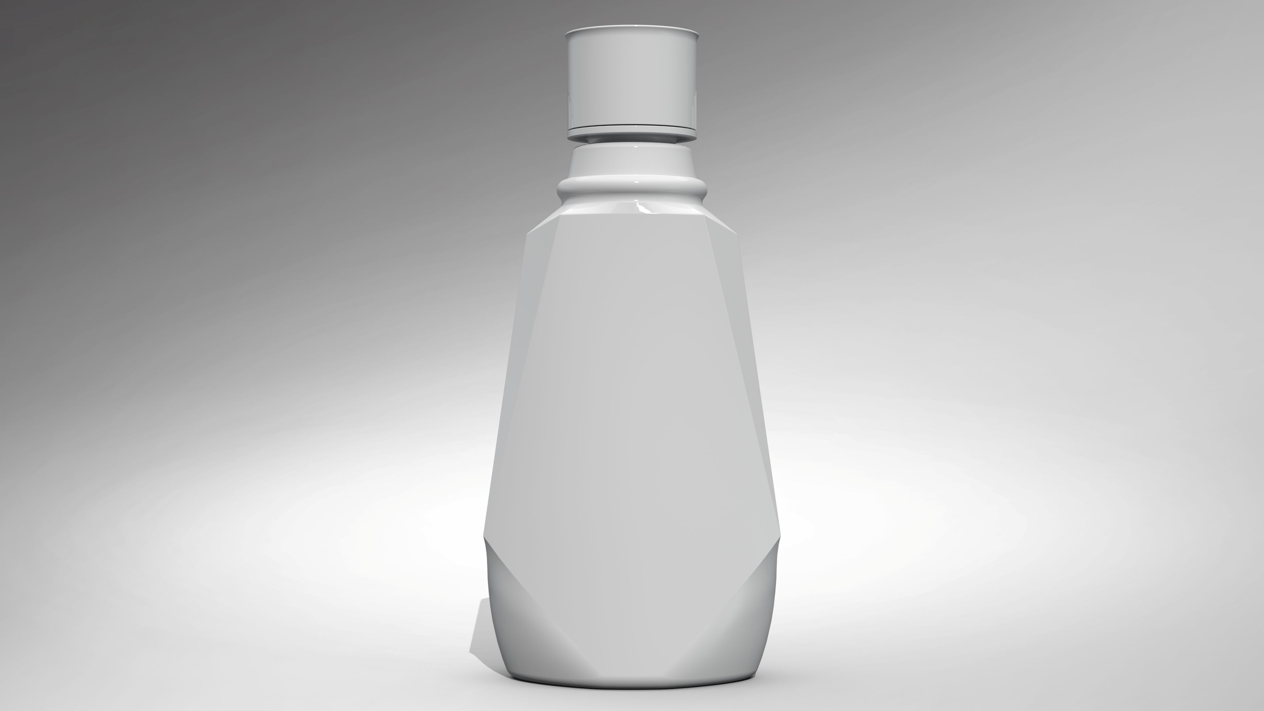
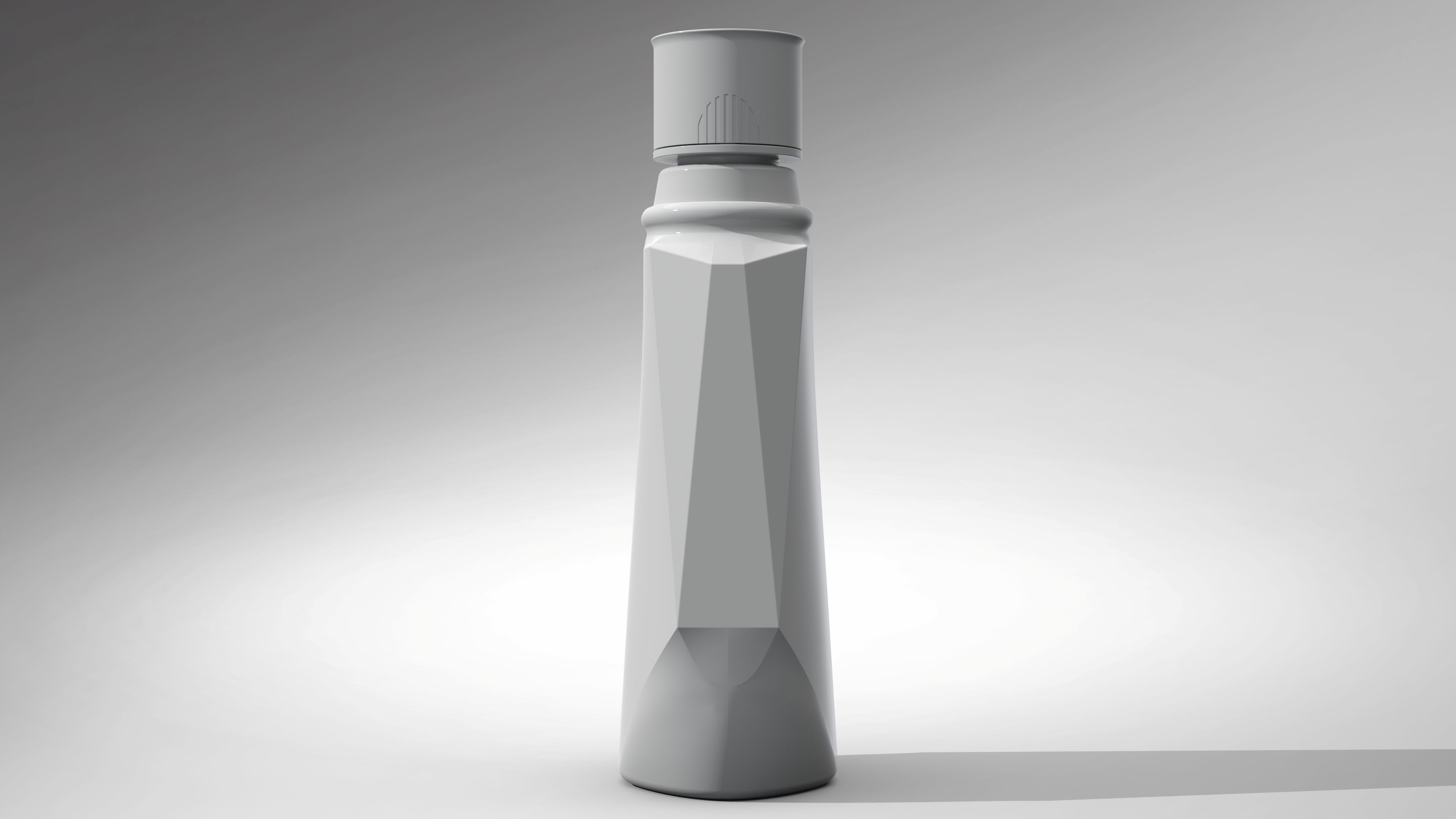
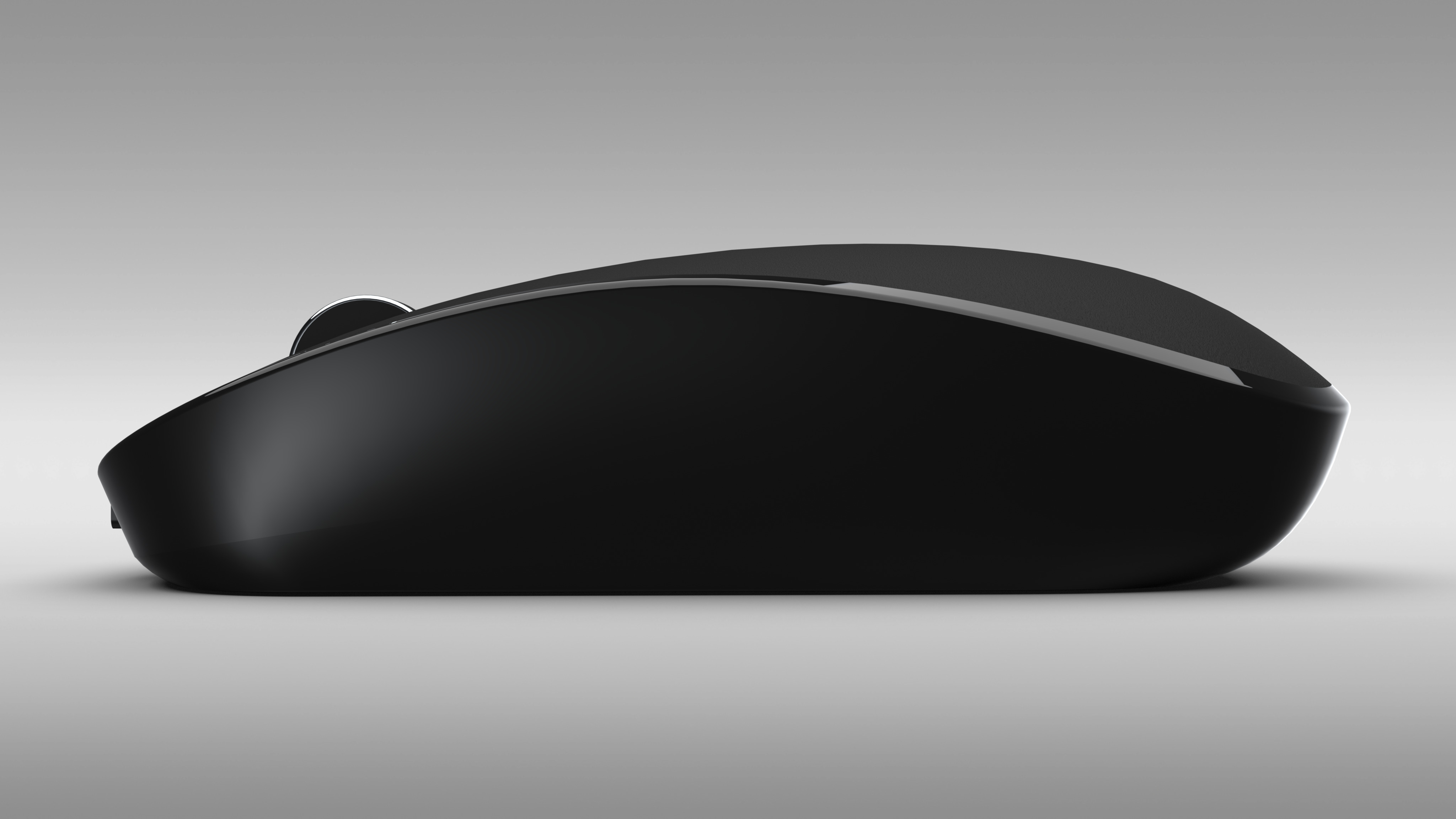
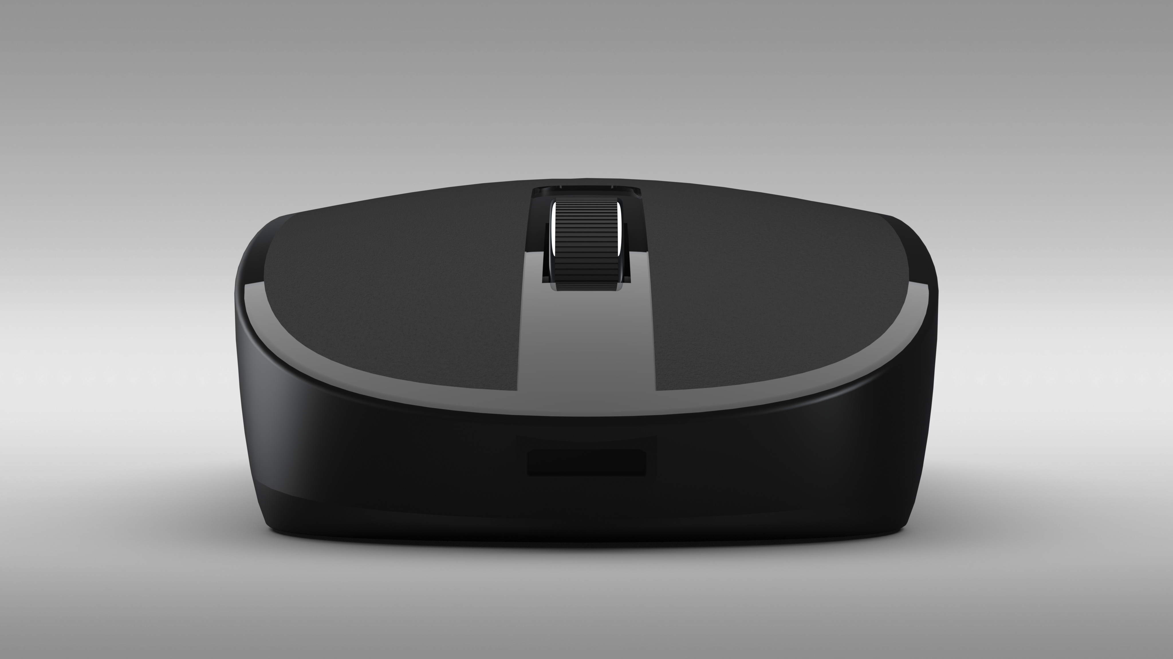
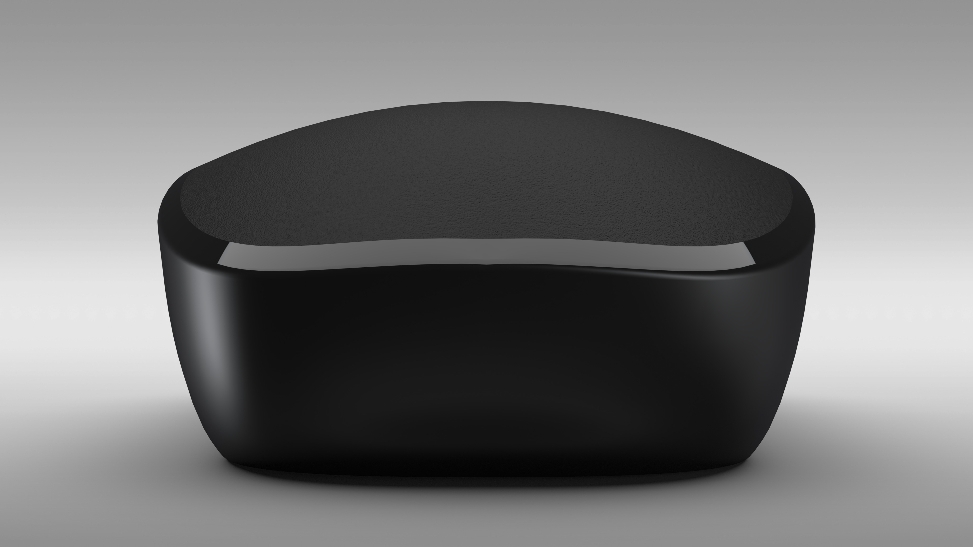
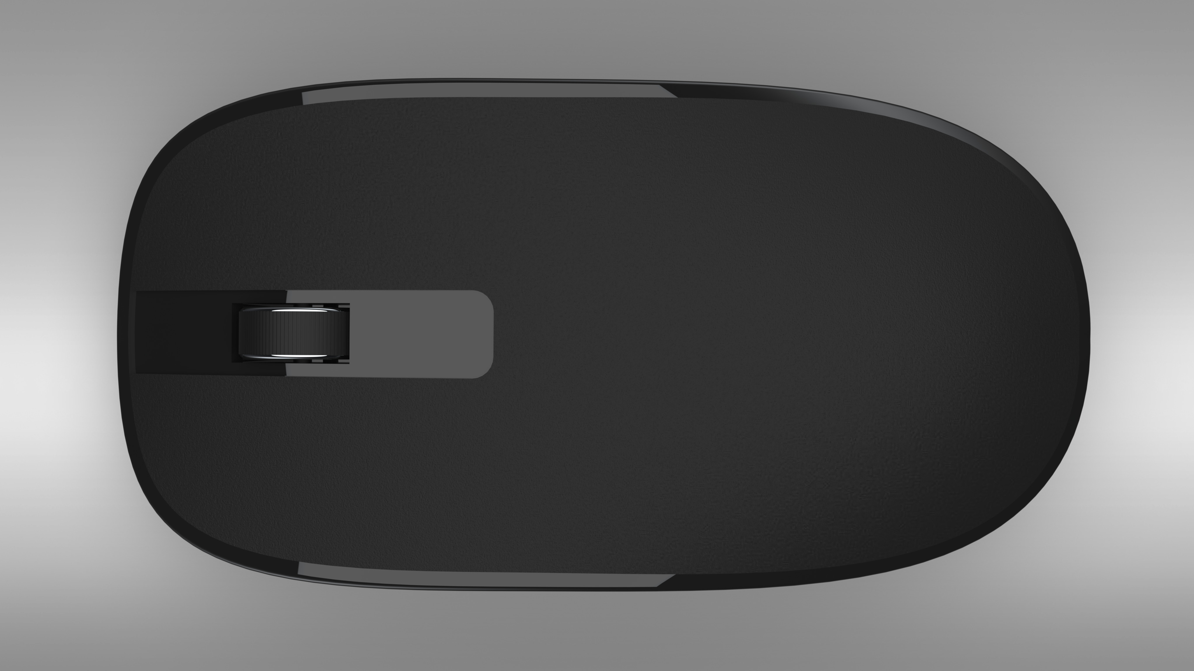
The mouthwash bottle was a deceptively simple project. I had been trying to create this object for a while but found it extremely difficult to capture all of the various geometry. After completing the mouse model, I used surface based modeling instead which turned out to be the easier approach.
Technical: The model was constructed from two reference pictures. Boundary and filled surfaces were the primary surfacing tools used.

-
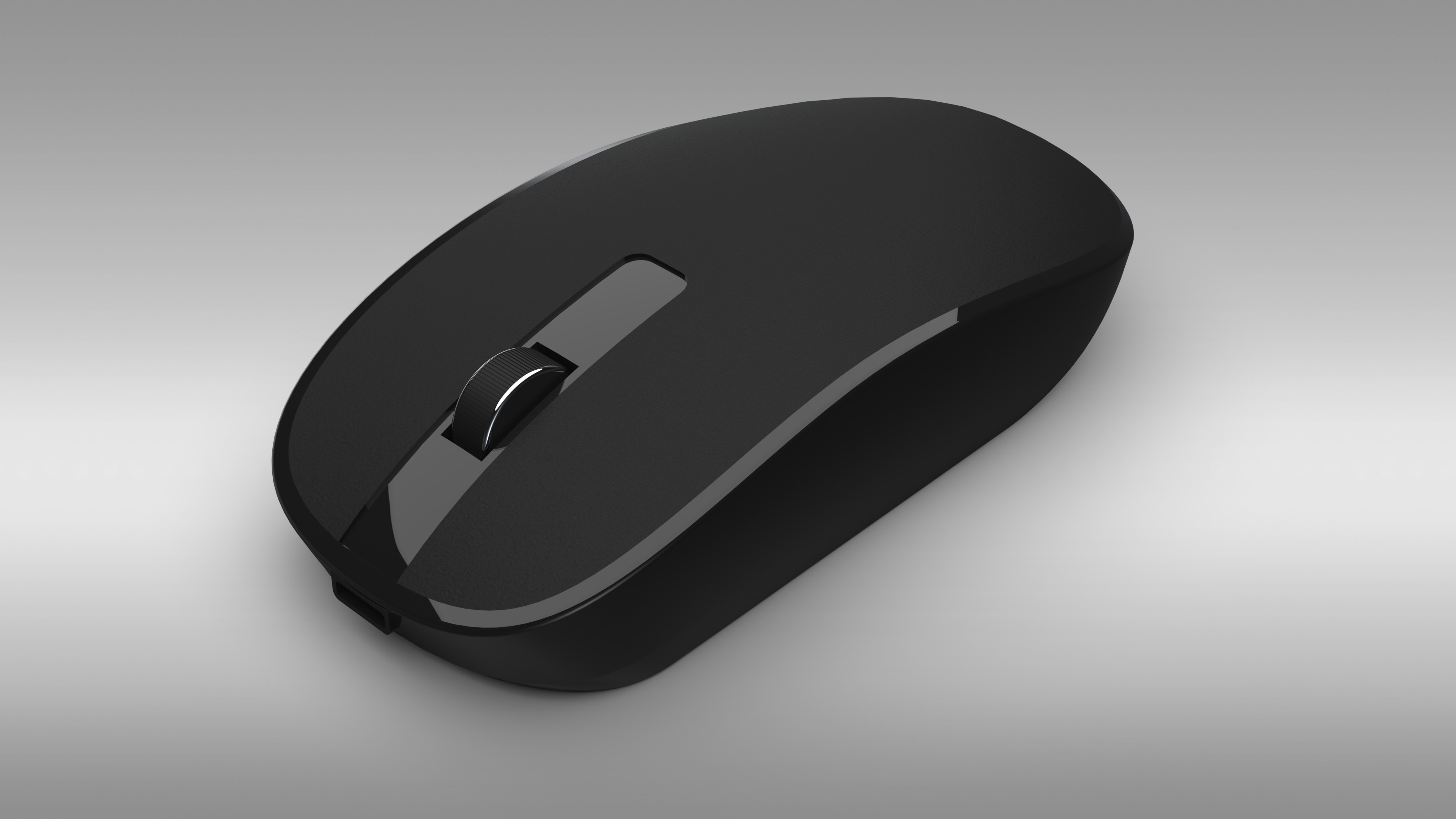
This model was an introduction to surface based modeling. The resulting render somewhat resembles the original object. Some of the curves and geometry did not quite match up to that of the original. However, I did learn quite a bit about the basics of creating “organic”/complex geometry.
Technical: The model was completed utilizing two reference pictures. Boundary surfaces were the primary surface tool used.
-
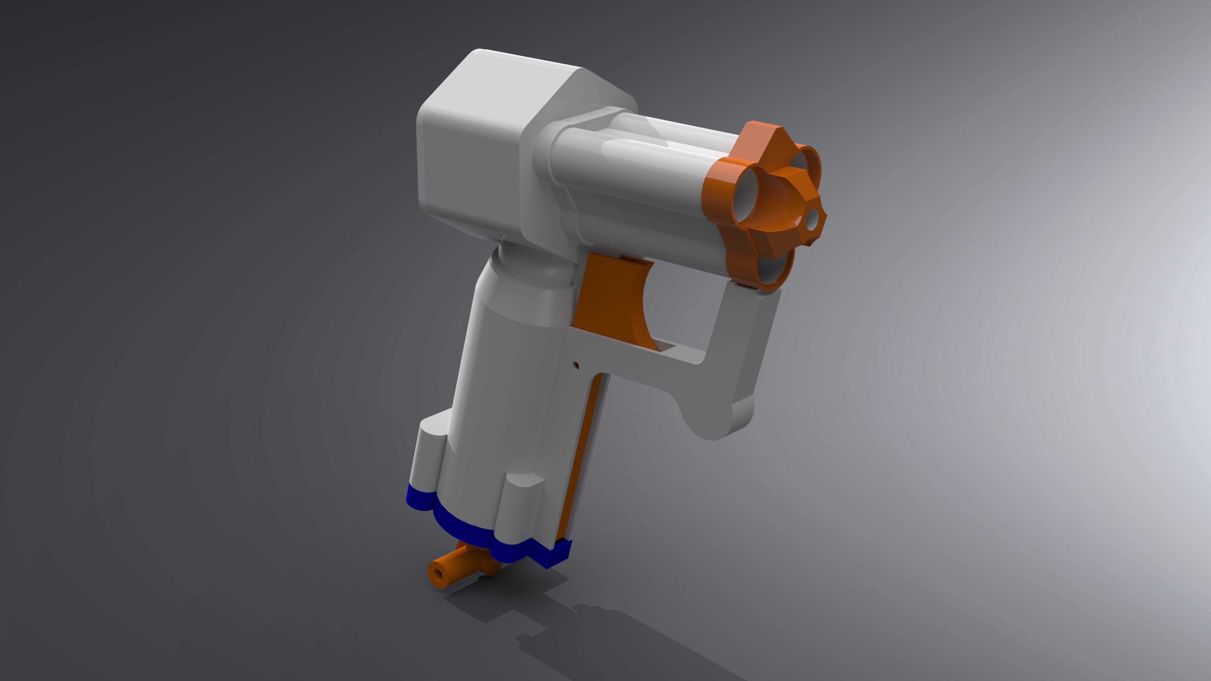
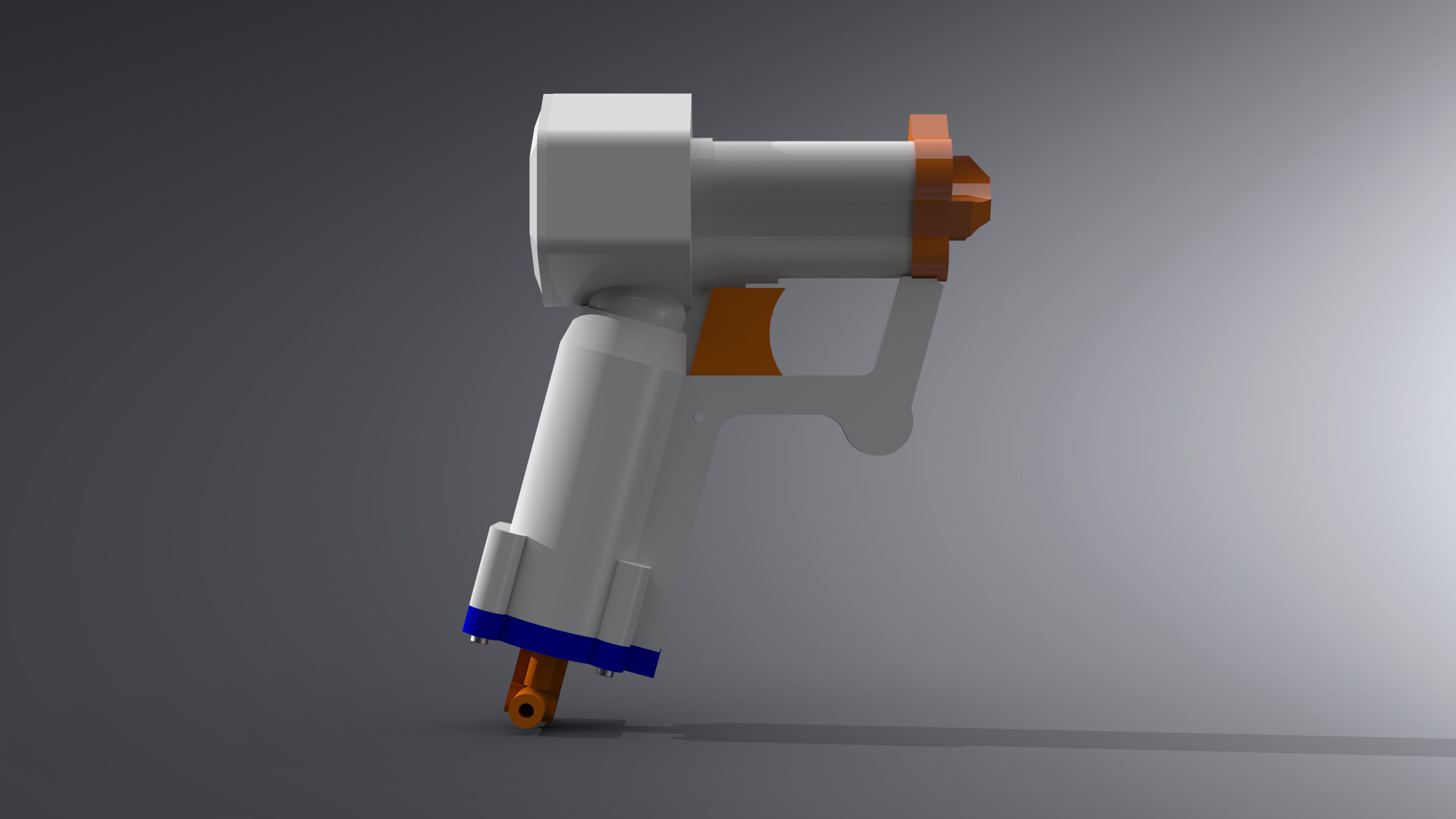
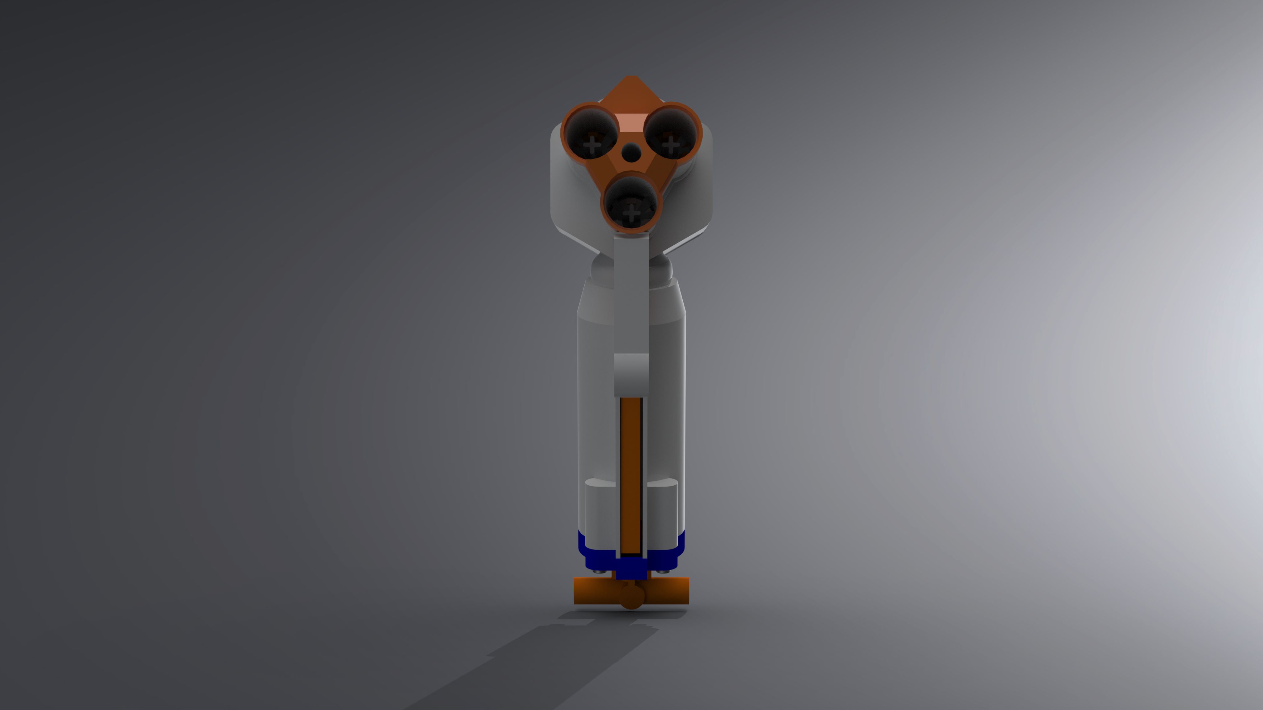
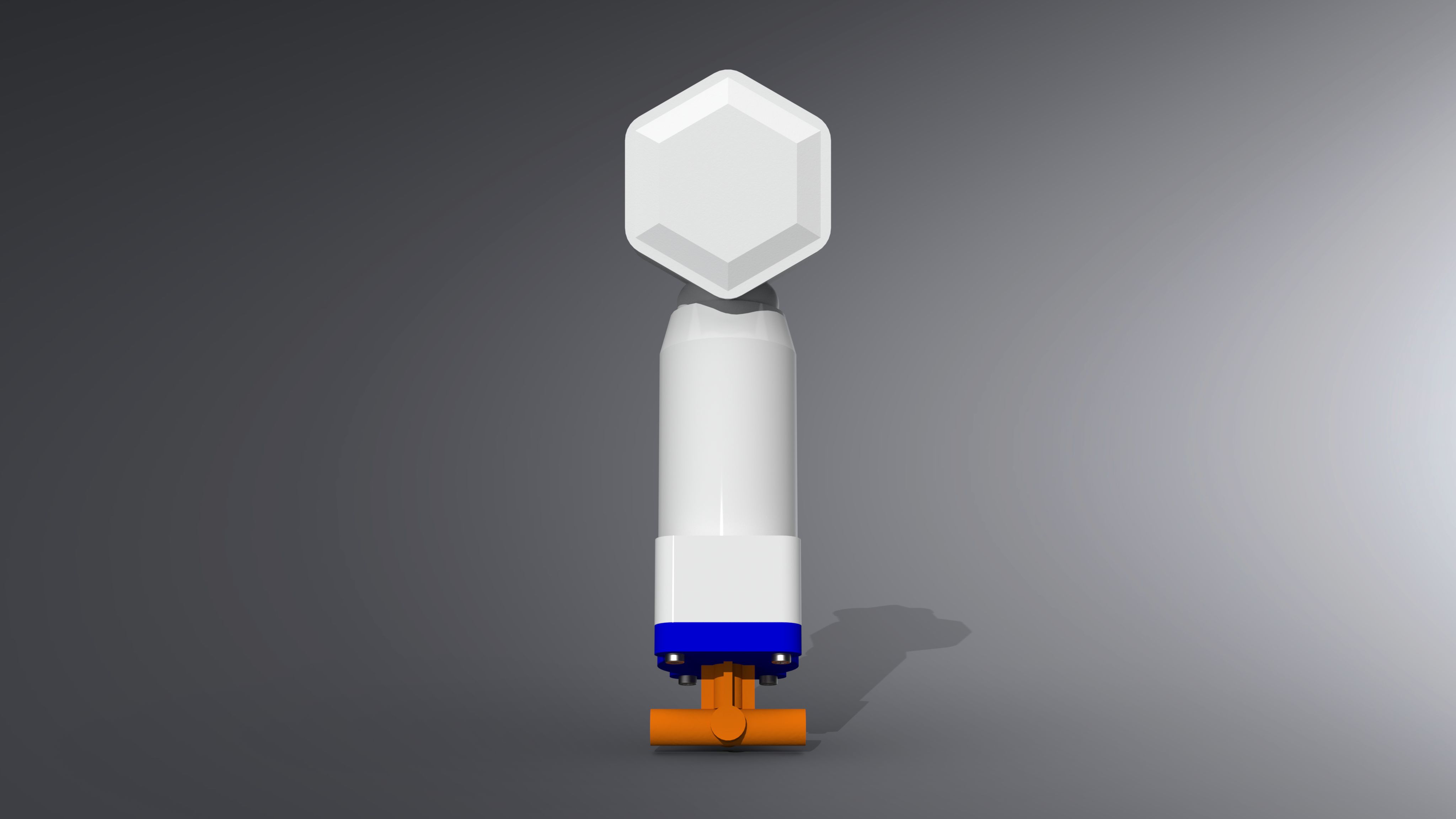
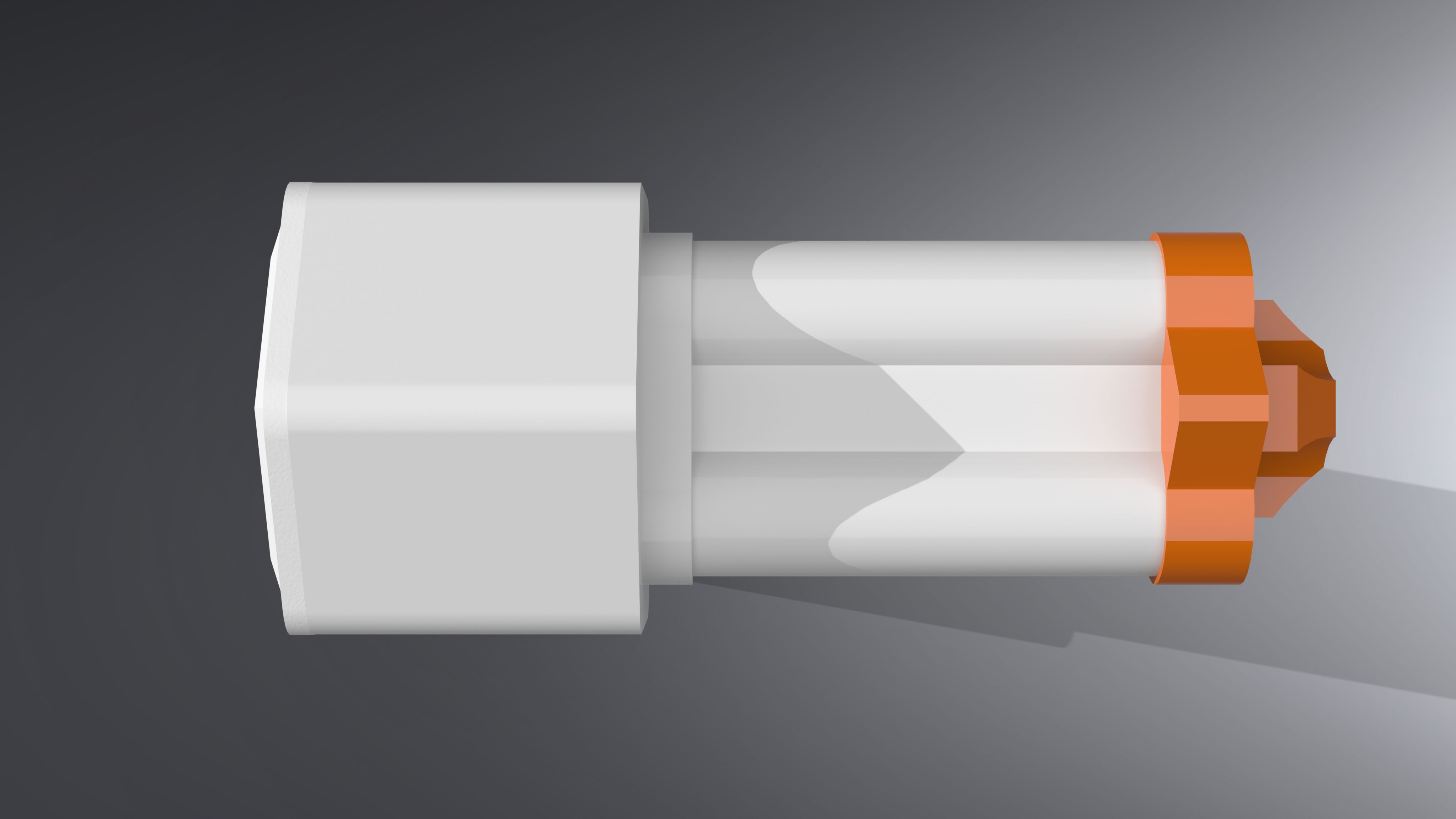
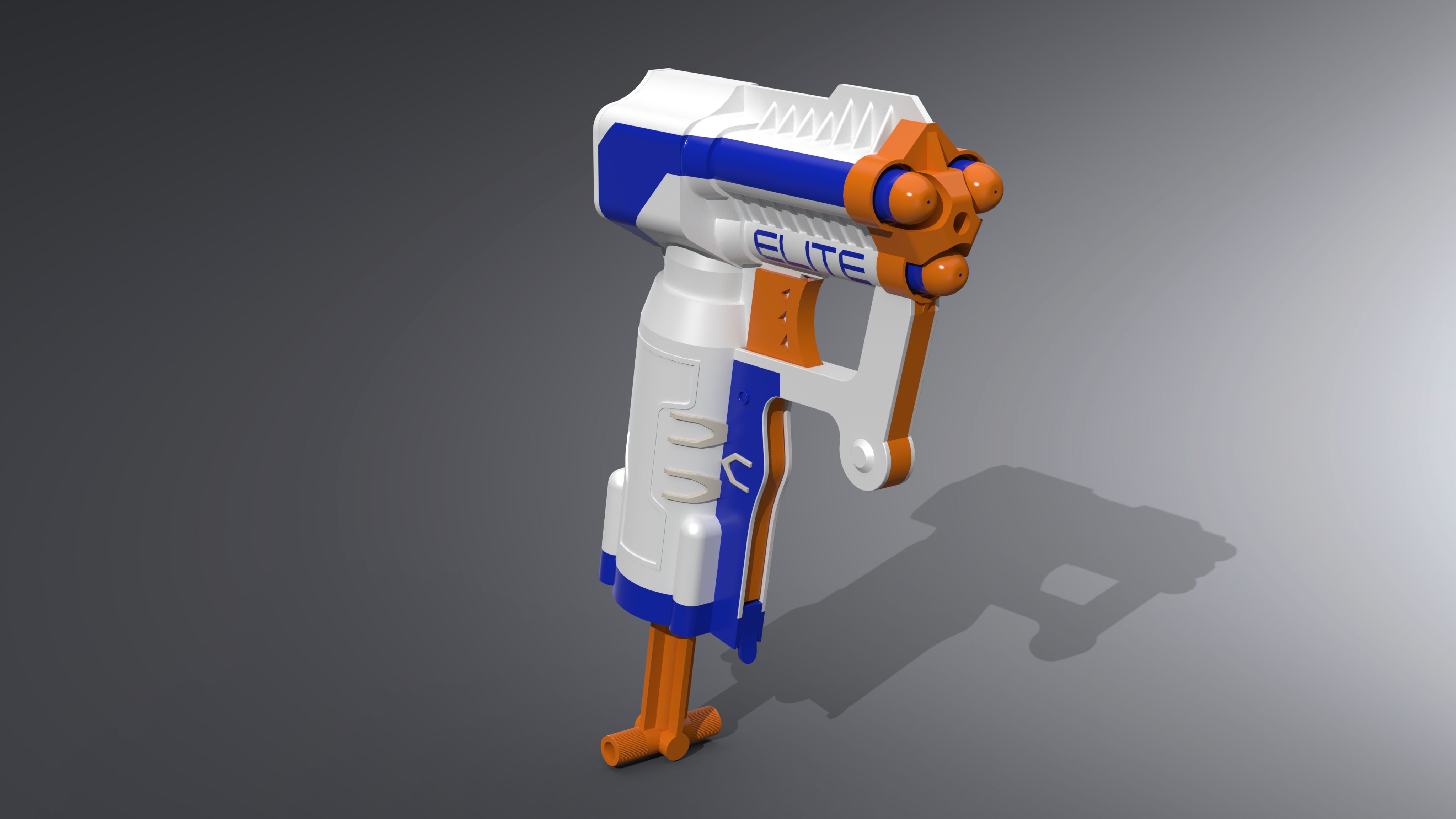
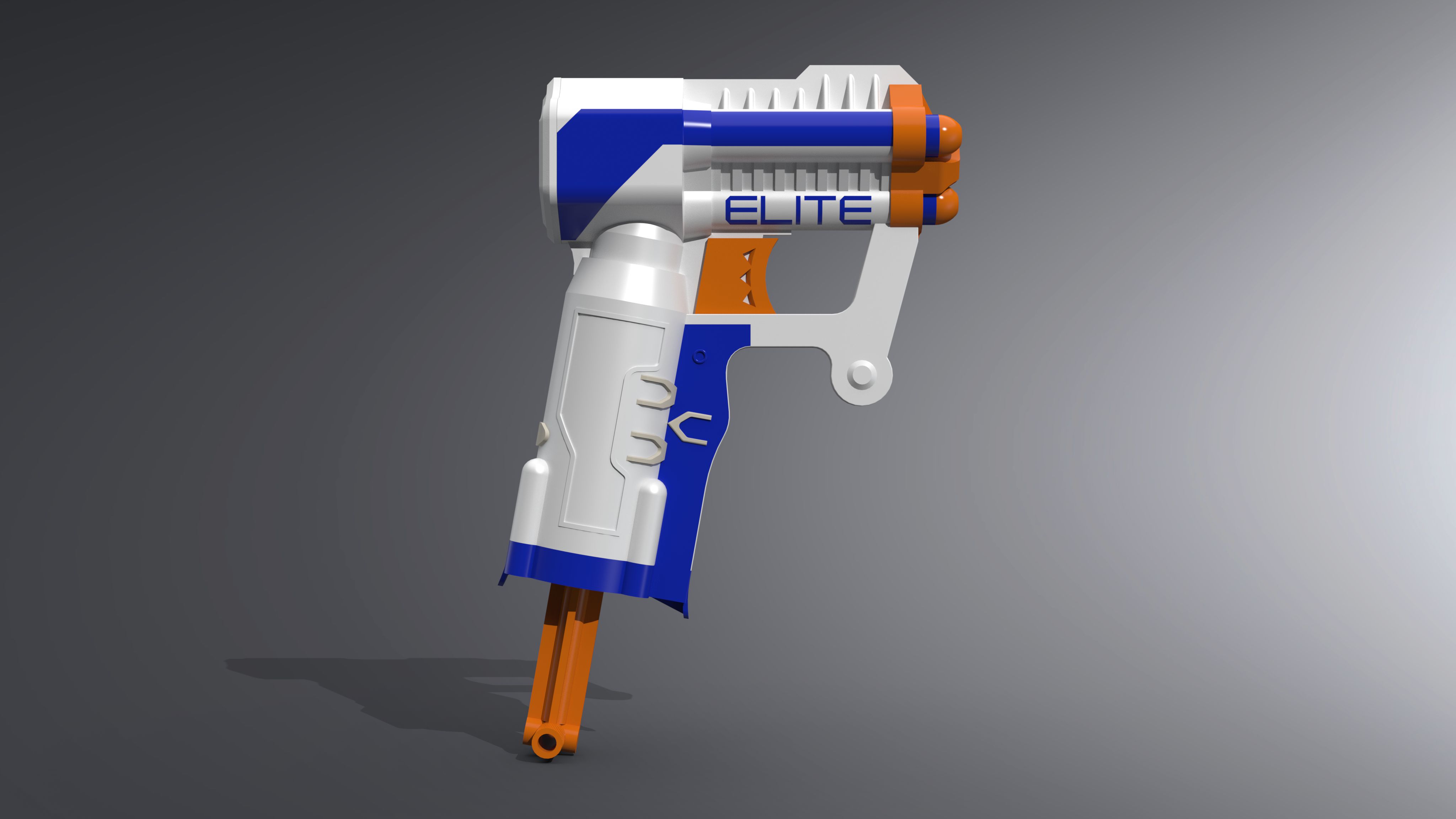
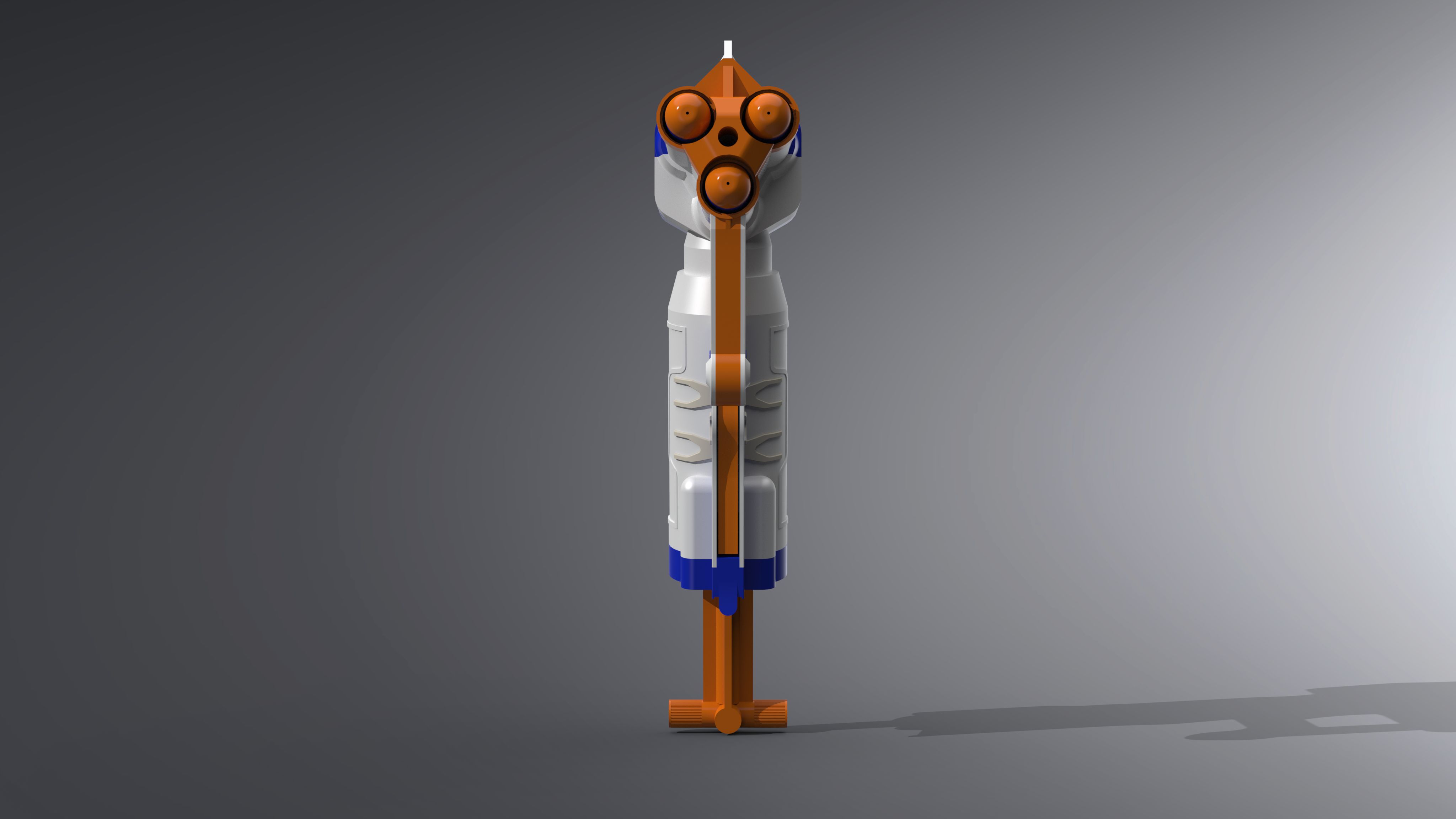
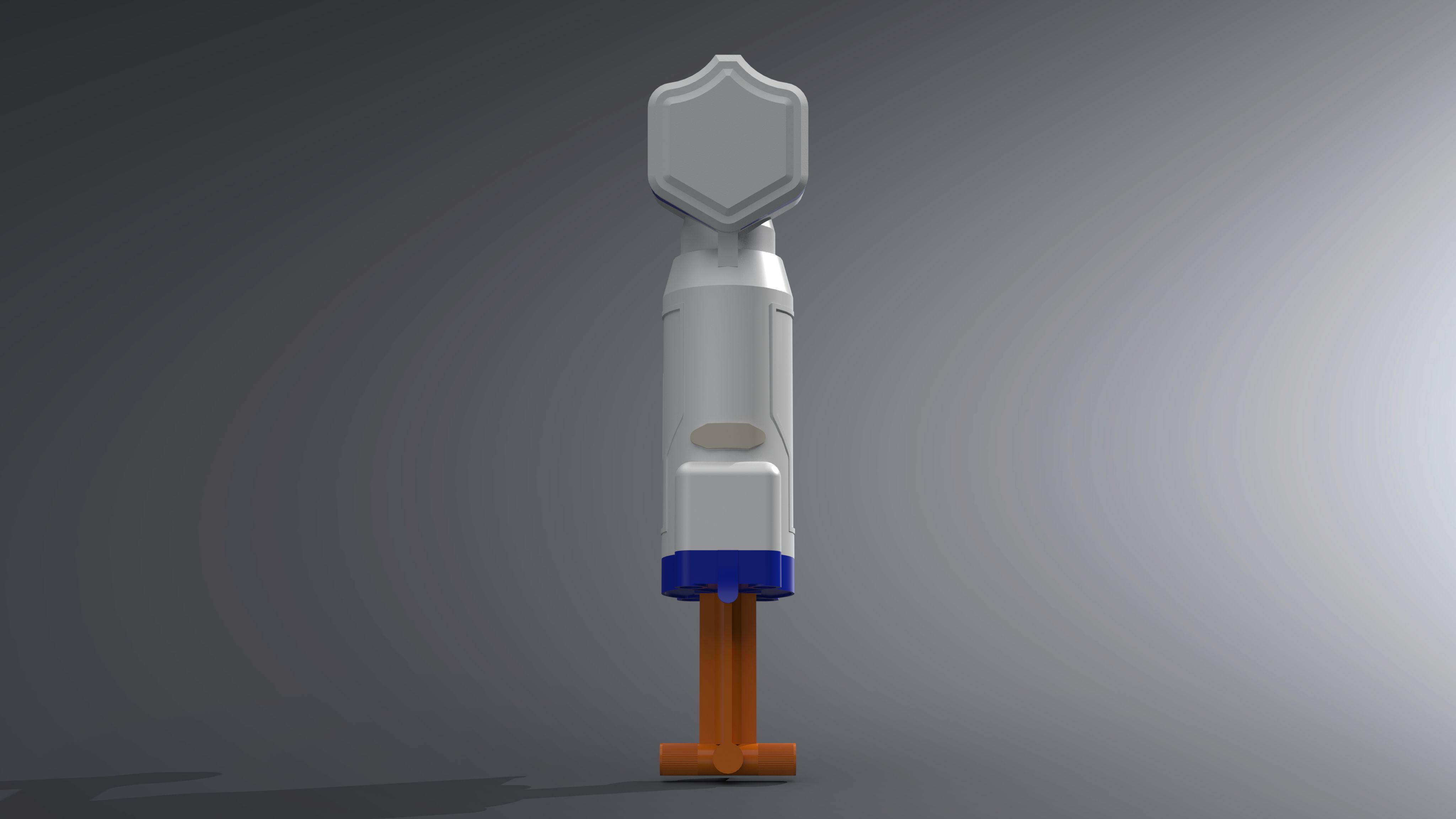
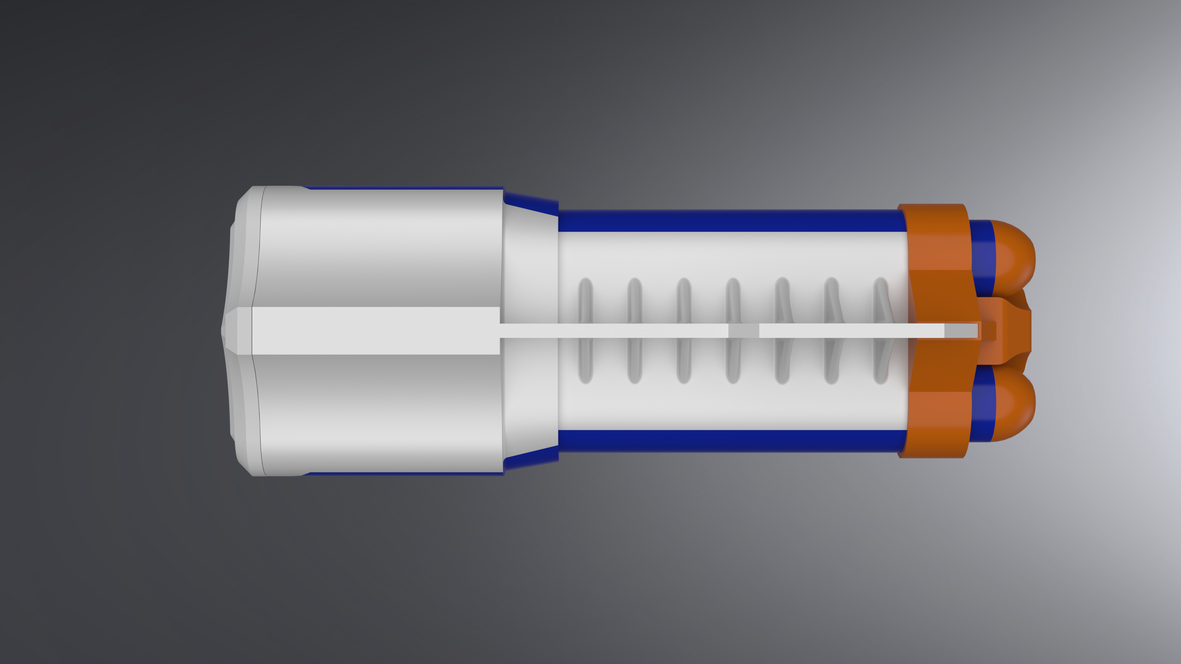
The revamped nerf gun model is a good showcase of the progress I’ve made. As seen in the original model, many details were excluded. In addition, some of the geometry was not accurate when compared to the actual model. Aside from this, the geometry was not fully defined and the design tree was unorganized for most components. These issues were rectified in the revamped model.
Technical: The model seen is an assembly of multiple different components. components were measured with dial calipers.
-
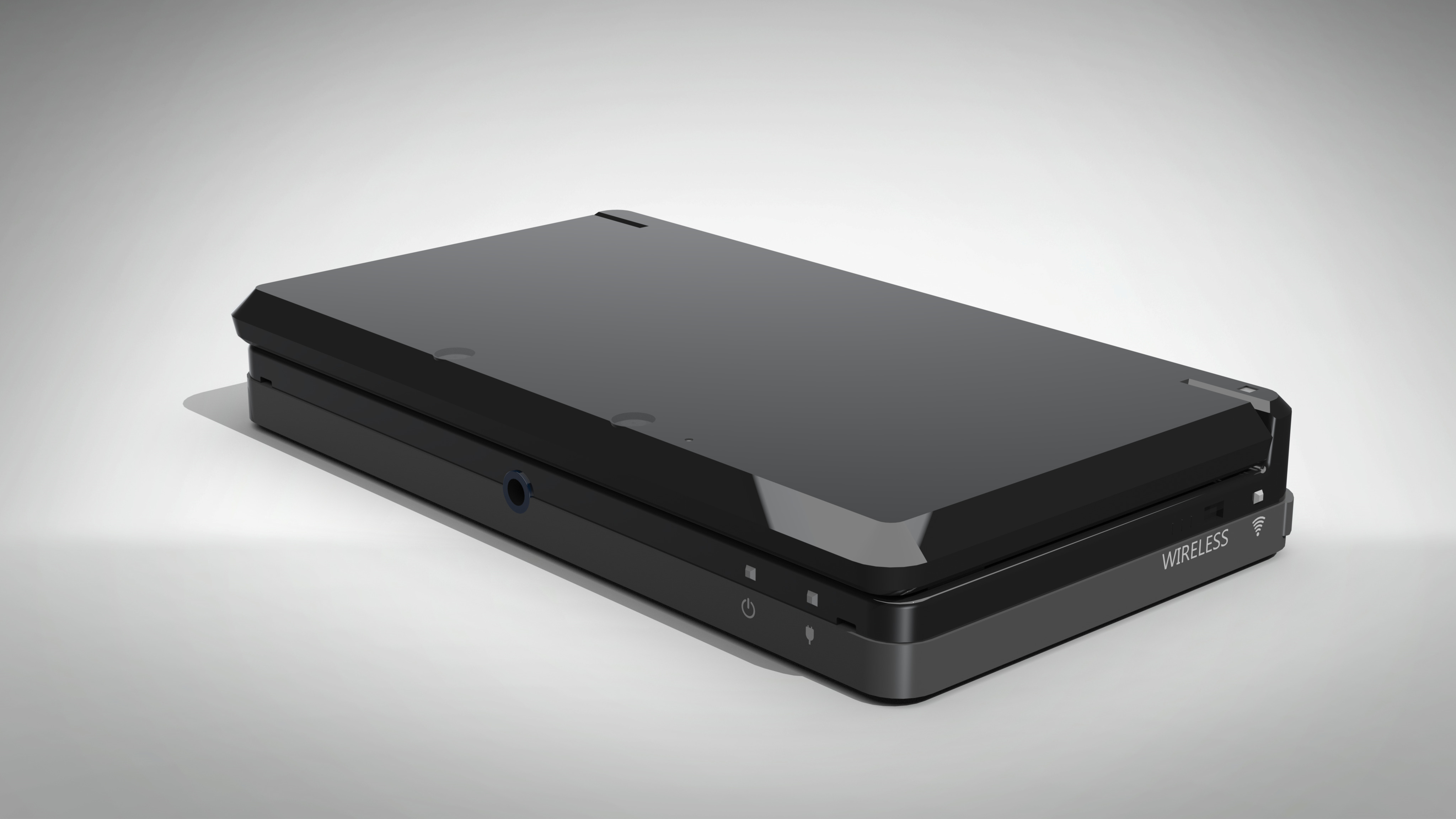
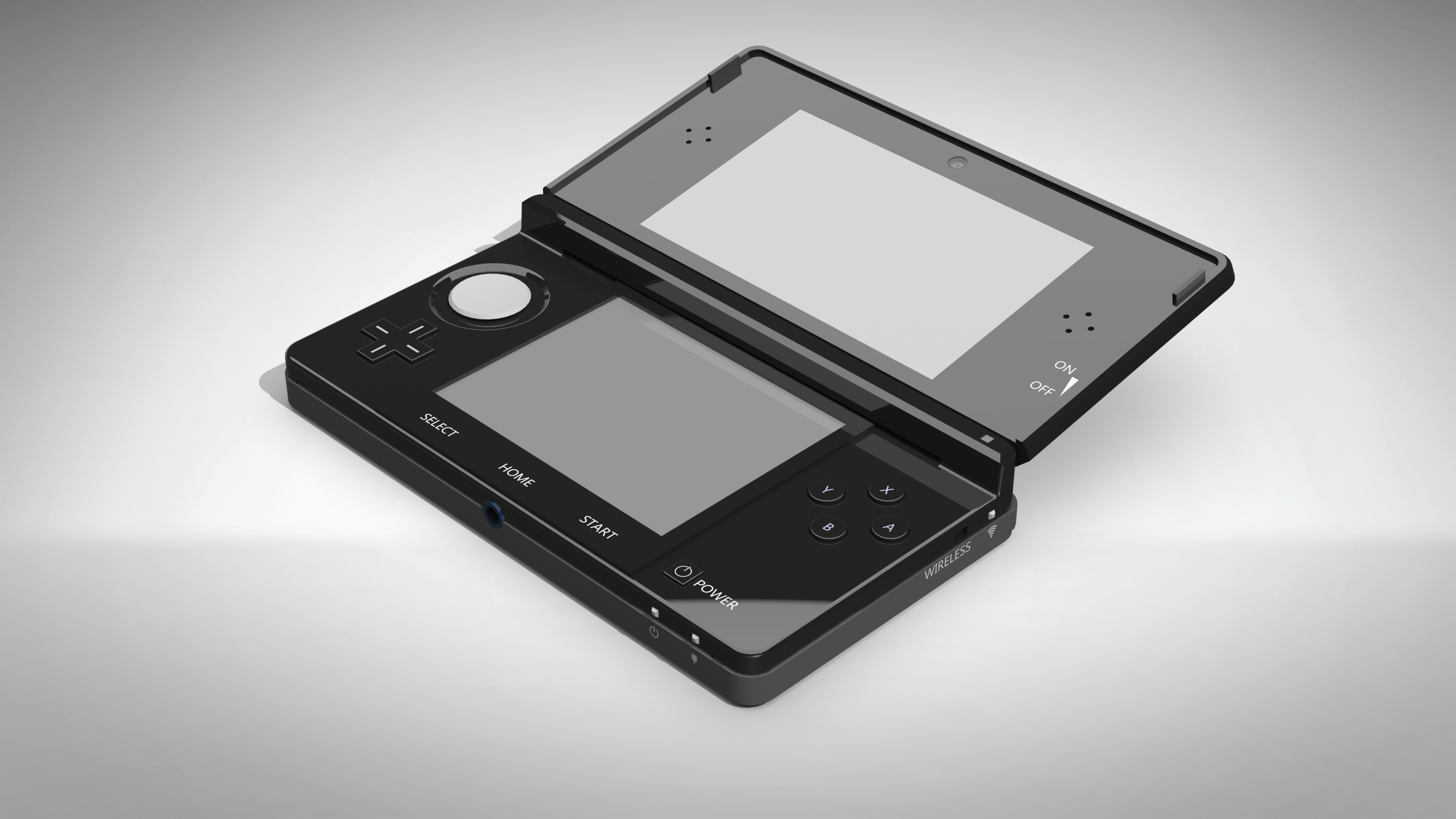
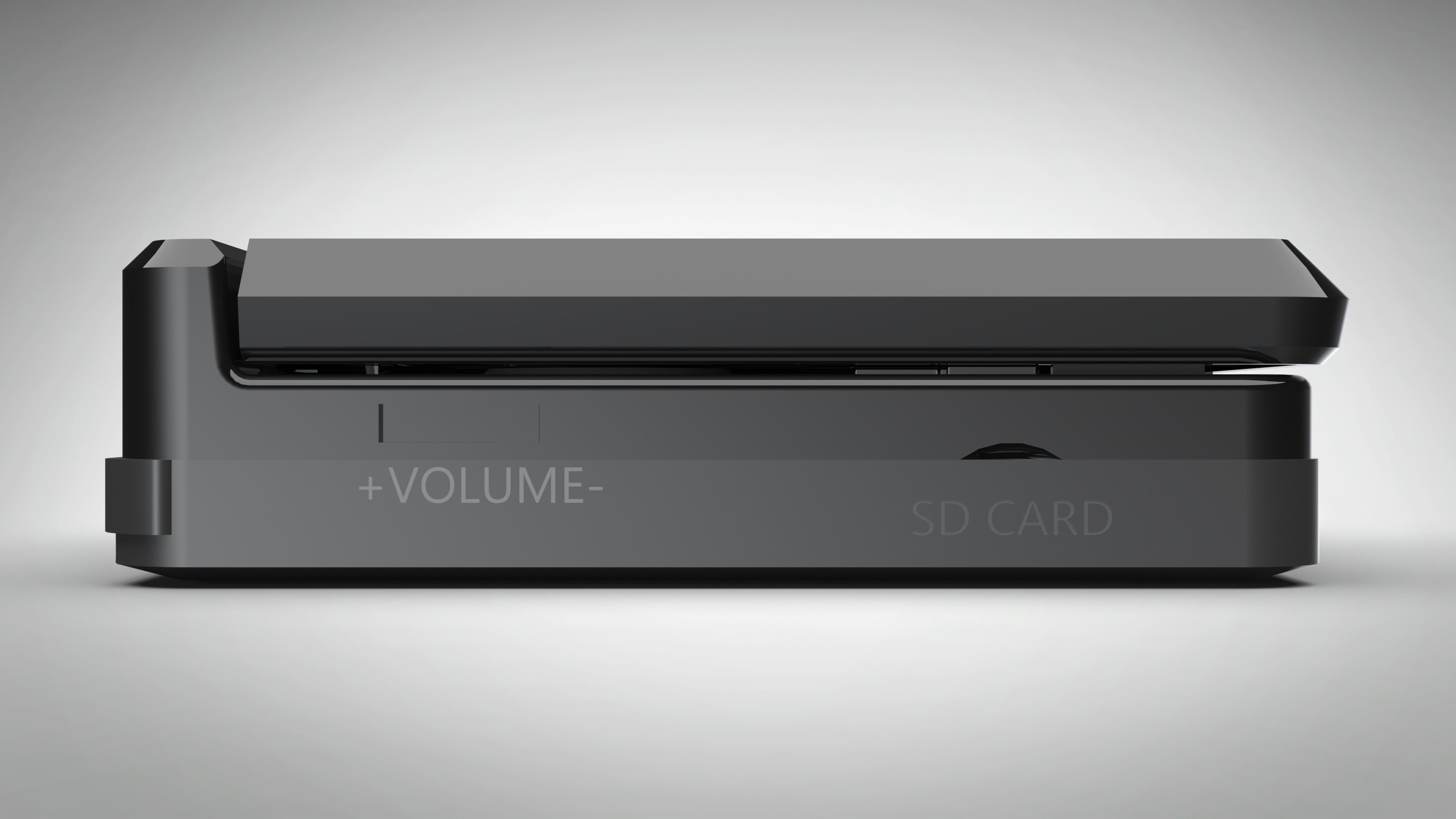
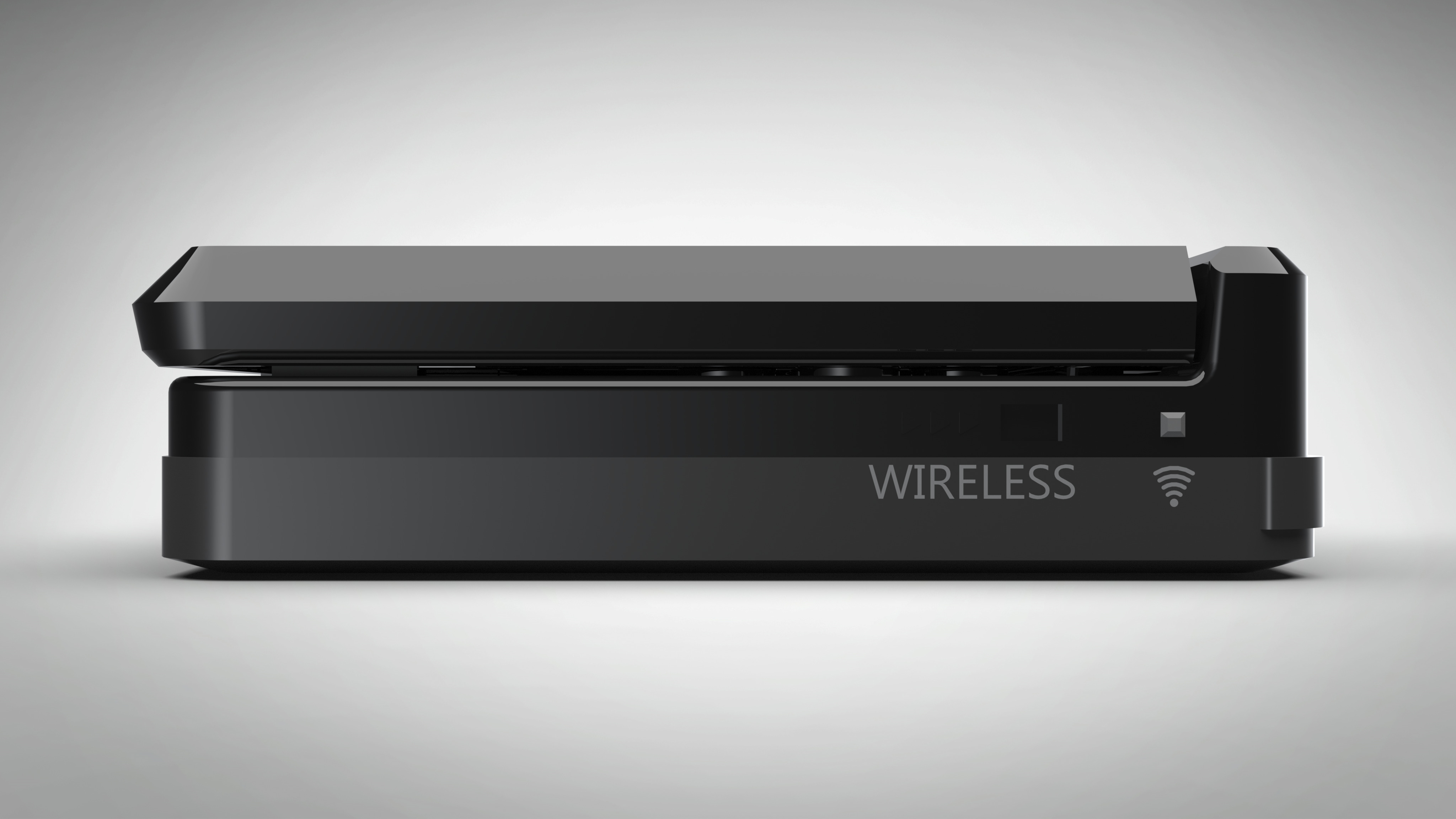
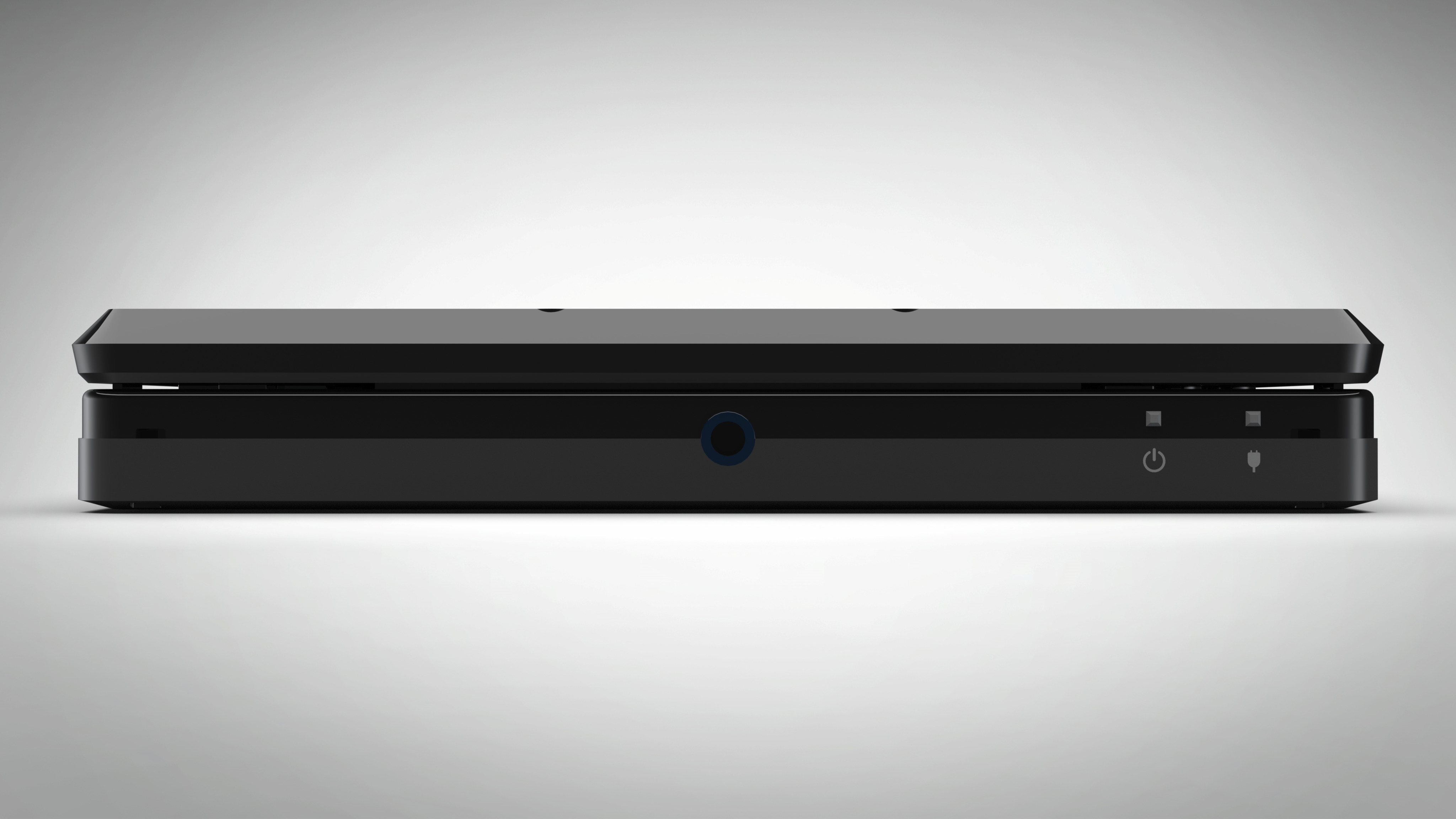
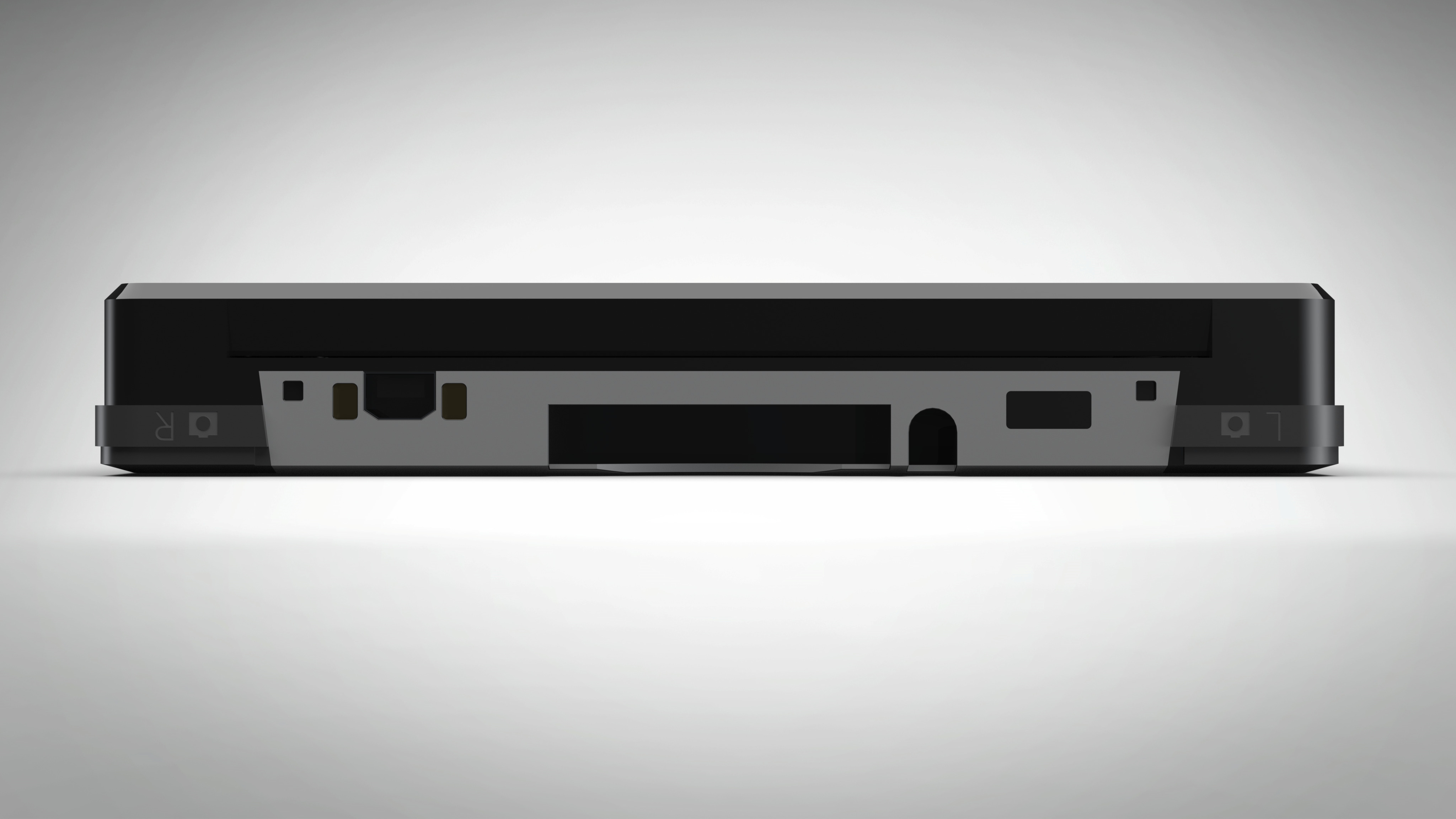
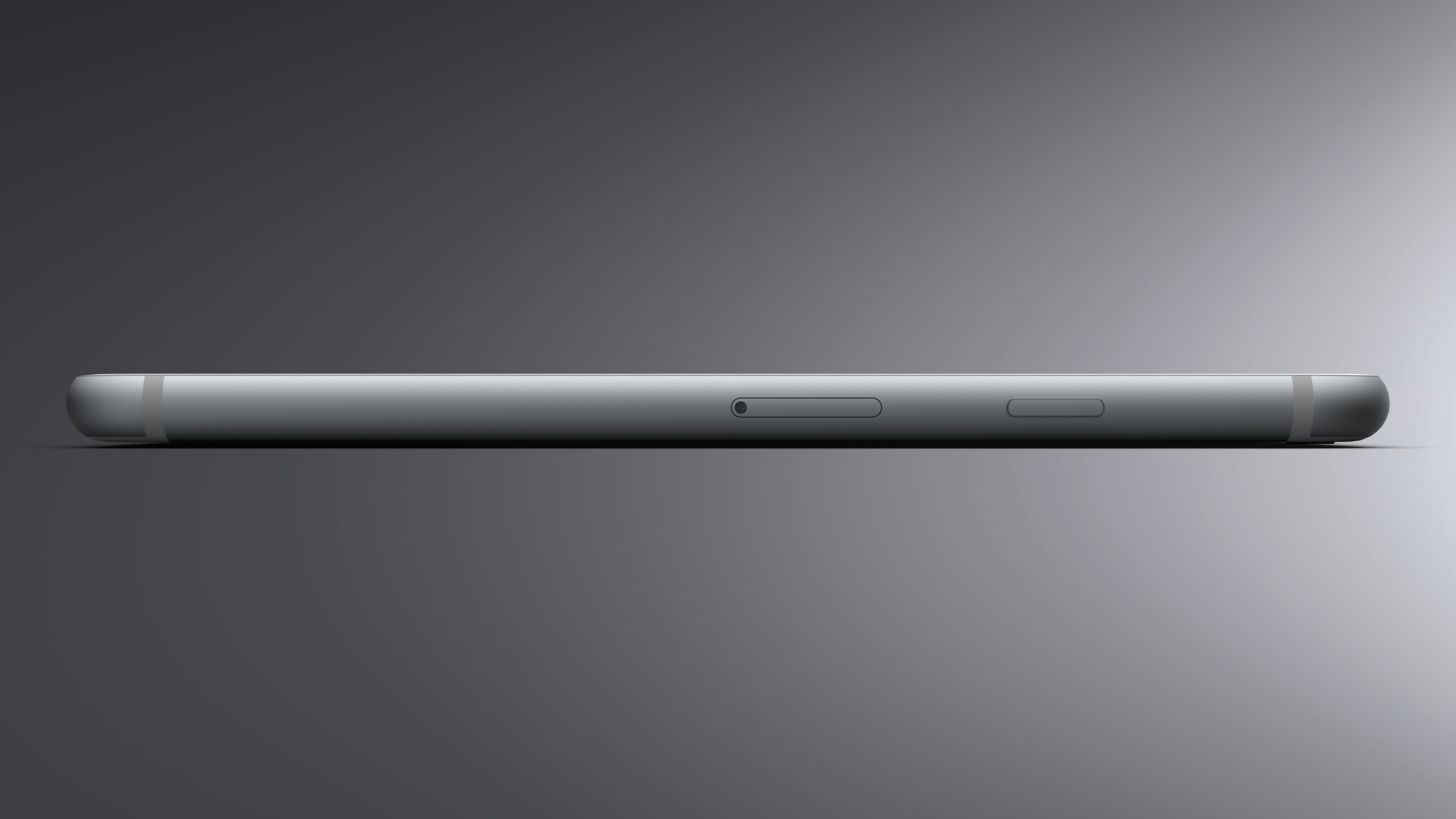
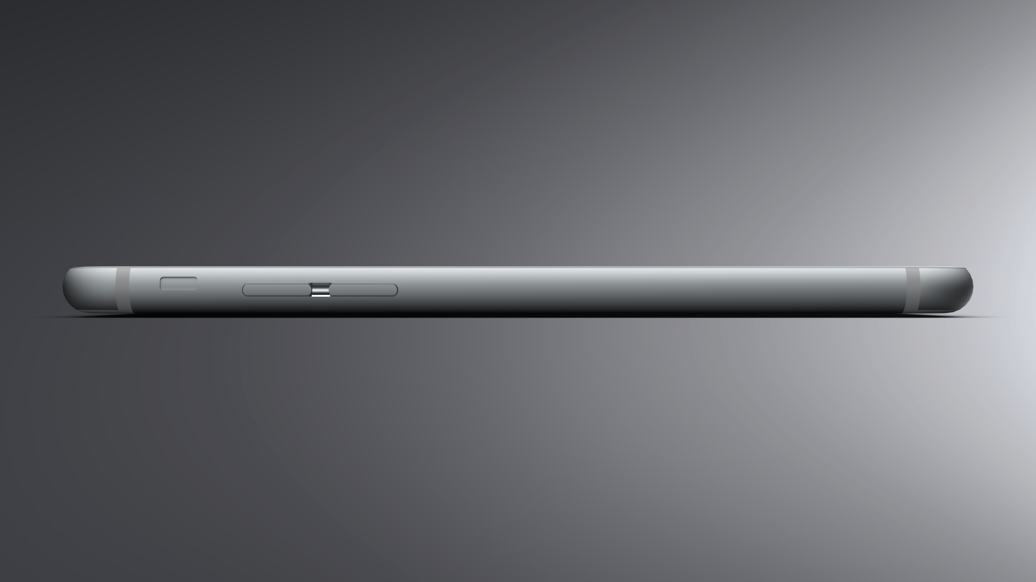
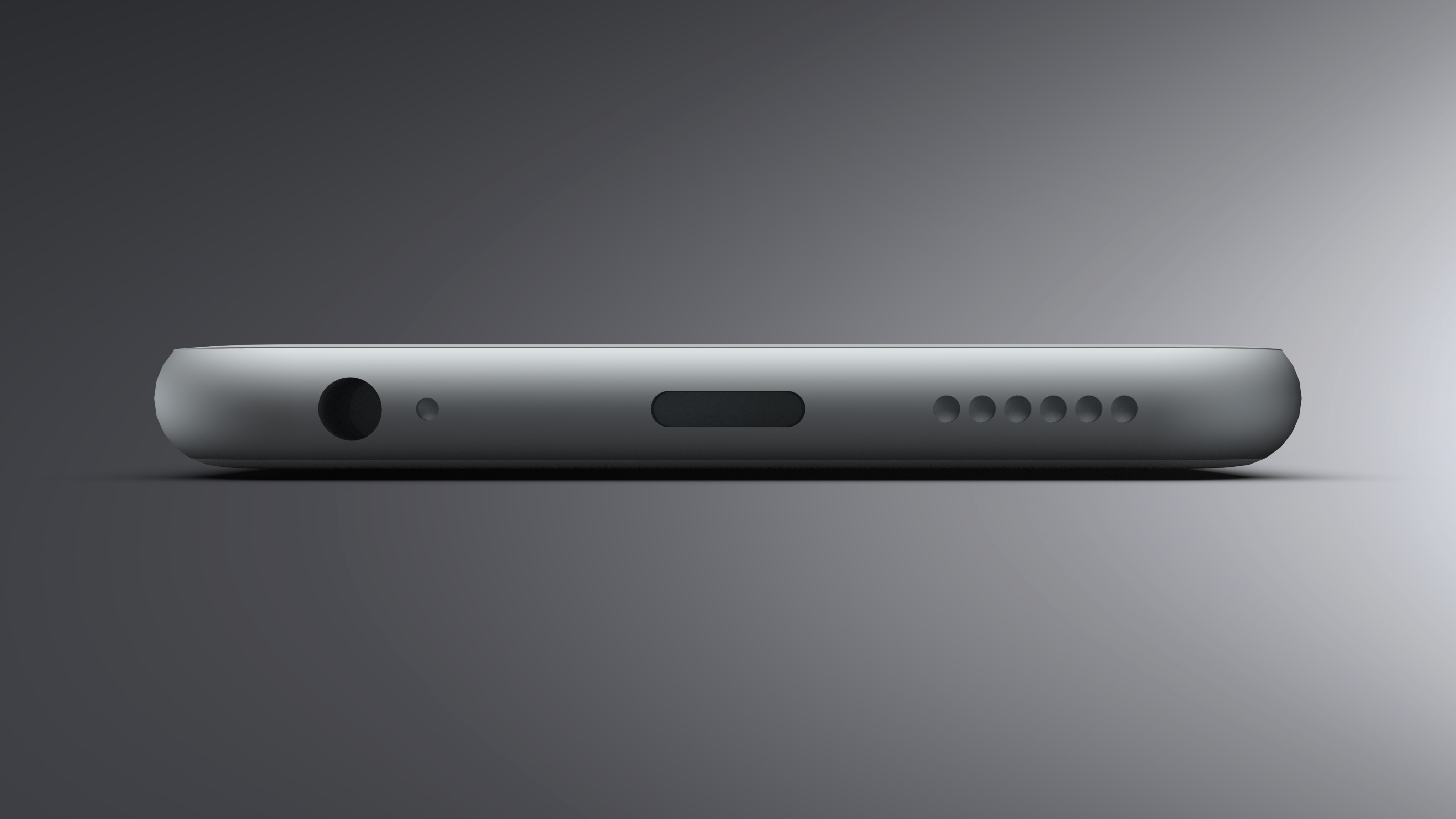
This was a model of my old smartphone. The model itself was relatively straightforward to create when compared to the other projects on the site. However, I am quite satisfied with the end product. I feel this render is the best out of all of the others in terms of resembling the original object.
Technical: A rectangular base was cut around its side to create the base shape. The volume and power buttons were done utilizing basic surfacing tools.


-
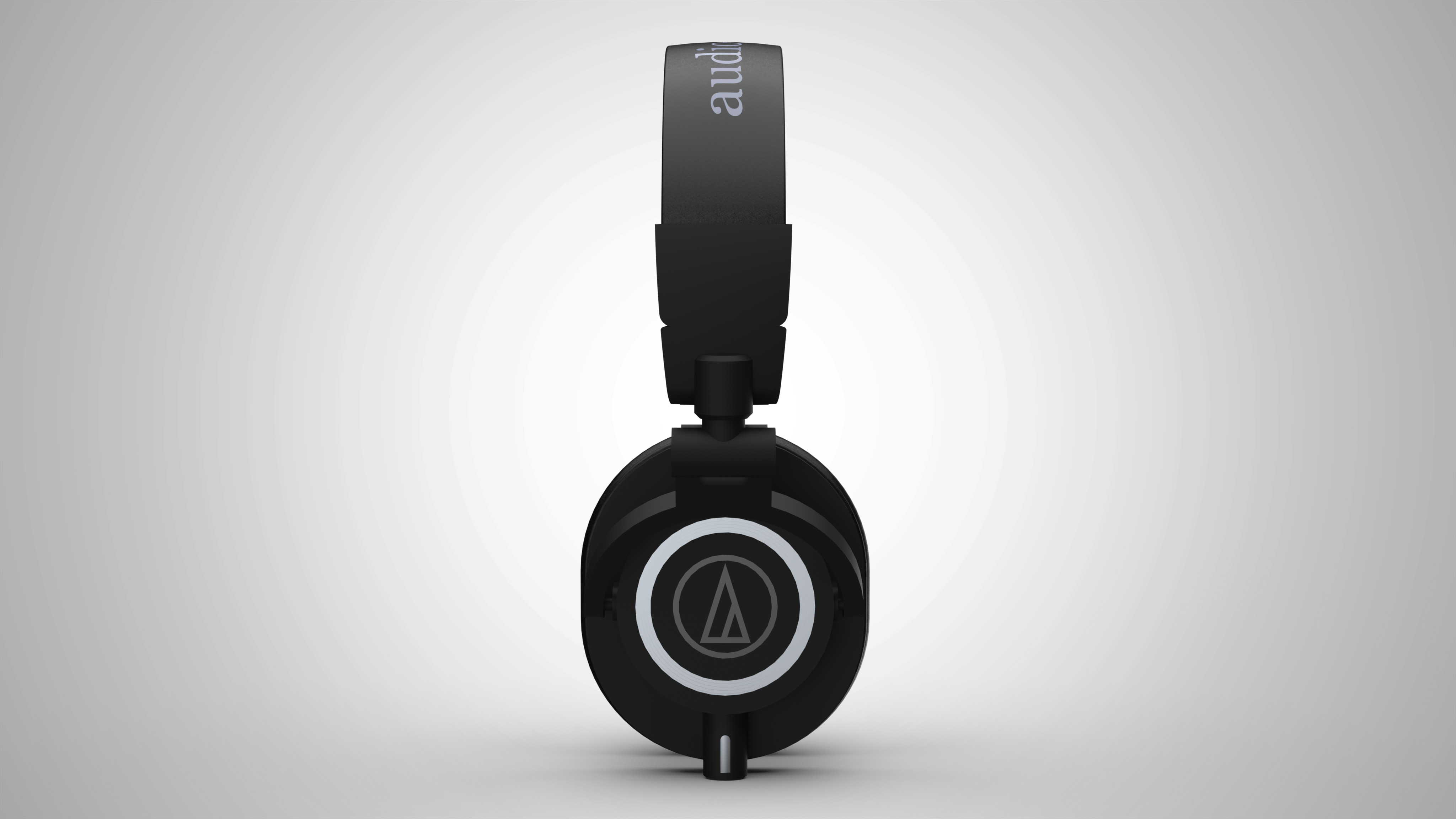
The headphones model was quite frustrating to create. The process of getting the individual parts to line up and move correctly was difficult at the time. However, it was worth sitting through the frustration as I was quite satisfied with the end product.
Technical: The model was made with basic modeling techniques. Some light surfacing was used for the headband portion.



Projects
-
The premise of this senior design project was to construct a lowering mechanism for an atomic force microscope (AFM). This project was the most challenging project I have undetaken throughout my time in college, but has provided invaluable engineering experience. In this project, I was the design lead and focused on the hardware side of things.
Problem
The AFM's being utilized by our sponsor are a relatively new product manufactured by ICSPI known as a "AFM-on-a-chip". The current setup that utilizes these AFM's are manual means that it can take a few minutes to lower the AFM to the appropritate position for a scan. In adddition, as these AFM's work on the micro and nano scales, very fine precision. The goal of this project is to create an automated device to complete the lowering process for the user to increase productivity and minimize the potential of damaging the AFM's themselves.
Concept Generation
The main focus of the concept generation was to identify was mechanisms our team wanted to implement for coarse and fine movement. We settled on the use of a linear ball screw actuator for coarse movement. As for fine movement, we had a variety of but ultimately settled on using a voice coil flexure system for fine movement after discussing with our sponsor.
Final Prototype
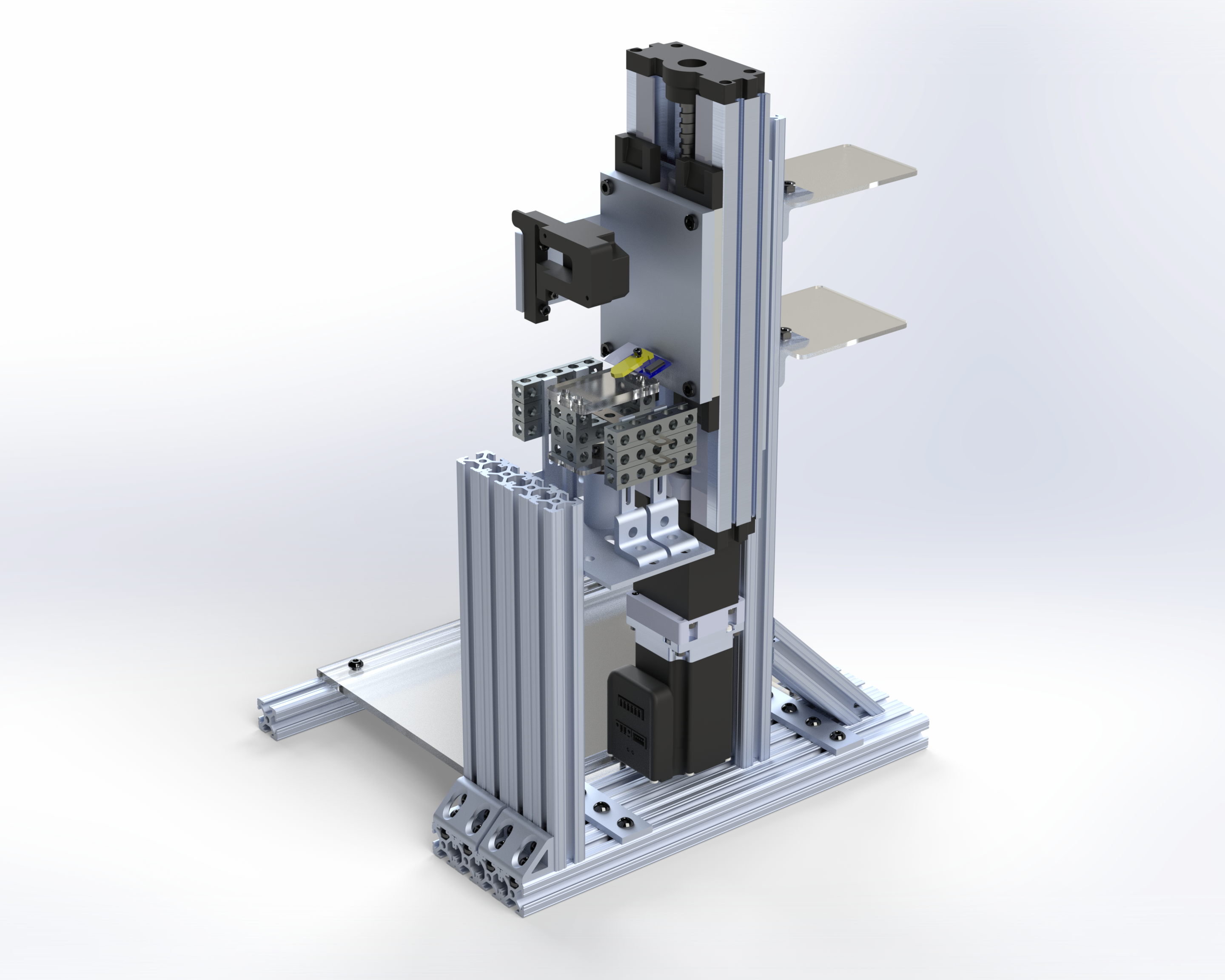
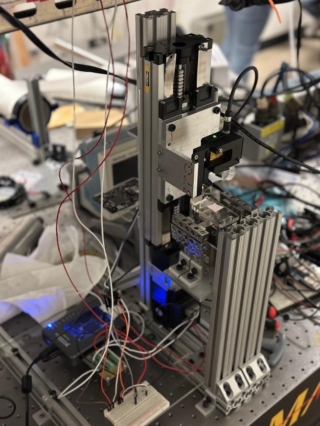
After fine tuning our design, the following model below was the final design we selected and was approve by our sponsor. The use of 80/20 aluminum provided ease of adjustment while being sufficiently rigid as a structural material. Plates were machined to ensure no flex or warping ocurred while under load. A distance sensor was used in conjunction with the ball screw actuator to make the coarse movement closed loop. As for fine movement, the AFM sends signals as it approaches a sample which essentially serves as a feedback signal that can be used for a closed loop system.
CAD Model:
Final Assembly:
Future Work
Although the physical side of the protoype was finished, not all of the software was completed. The software was done through LabView. The closed loop program for the coarse movement was completed, but the fine movement closed loop program was not completed. However, the program itself was layed out such that the time needed to finish the program is minimimzed which was okay with our sponsor.
-
The premise of this senior design project was to make and prototype an autonomous instrument for a K-12 audience. The final device was required to play at least 3 different songs without human interaction (e.g. press a button and the device will automatically play a song) and must not exceed a cost of $250. The sections below summarize the major sections of the project.
Project Proposal
The first section of the project was creating a project proposal to outline the projects purpose and how we intend to approach the problem at hand. For part of the project proposal, background research was conducted find inspiration and establish previously done autonomous instruments. The main component of this section invovled interviewing an audience to determine key features or requirements for our design. After analyzing the interviews, we established the following as our primary goals for our design: "the automated instrument must be optimized in both form and function, produce high fidelity sound, and be able to be used for a wide range of educational purposes."
Design Review
The next section invovled figuring out the subssytems required to automate an instrument and brainstorm designs incorportaing those subssytems. After constructing a mind map and functional model to define various subsystems, we bagan to sketch some preliminary designs utilizing the 6-3-5 and further streamlined the designs using through a morph matrix. We then compared the six designs generated by the morph matrix using a pugh chart. We also created a low resolution prototype of a potential design, but this was later scrapped in favor of a different design.
Final Prototype
The last section of the project consisted of actually building a working protoype. The final design we settled on was relatively simple design to ensure that time and budget constraints were met. The design functions as follows: 8 solenoids, one for each note, would be sent a signal from an arduino to momentarily activate. The solenoid would retract and pull a string. The mallet, which is attatched to the string, would then strike the instrument and produce a note. The song was then hardcoded into the Arduino software. Throughout this section of the project, multiple different tests and analysis were also conducted to ensure our design/prototype met requirements or would function as intended.
Personal Potenial Design Revisions
Videos
Jingle Bells
Carry on Wayward Son
Thriller
-
In this project, we made our own rc car. We had a given budget of 50 dollars. The goal of the project was to create a functional rc car while applying concepts learned in class to help design the rc car.
SolidWorks model:
-
The premise of this group CAPSTONE project was to create a circuit that did the following: the circuit would take in the AC signal generated by the windmill (an external fan spins the windmill) and determine whether the windmill is being spun too slowly or quickly via LED’s. An additional LED, which is always on, dims or brightens depending on how fast the windmill spins.
Before constructing our circuit on a breadboard, we first built the circuit in NI Labview.

As seen in the picture above, the circuit we made was composed of 3 systems: a rectifier, logic controller, and indicator.
The rectifier was made using an external DC voltage source, capacitor, and resistor. By placing these components in parallel, we were able to turn the AC signal generated by the windmill into a usable DC signal.
The rectified signal was fed into logic controllers and an indicator. The logic controllers were constructed with a comparator, a potentiometer and external power source that served as a voltage divider. The voltage from the potentiometer and that of the rectified signal were compared. Depending on which voltage is greater, the signal would or would not be allowed through. For this reason, two logic controllers were used. One classifies a signal that is too quick and the other classifies a signal that is too slow.
The bottom indicator was constructed with a transistor. With the transistor, depending on the voltage of the rectified signal, the LED would dim or brighten.
This project was a great learning experience in working with circuits. In addition, it was a good opportunity to test the knowledge we gained through the semester. Building the circuit was like solving a puzzle, it was quite enjoyable.
-
The goal of this program was to build a program which would solve a Sudoku puzzle. Alongside the code, I made a basic GUI which allows for the input of a Sudoku puzzle. The basis of program is to try and solve the puzzle systematically like a a normal person would. To do so, a lot of matrix manipulation and list comprehenshion was used. This is the approach I took due to my limited knowledge in Python. I avoided tutorials but did use stackoverflow to help with some of the list comprehenshion.
However, not all Sudoku puzzles can be solved with regular techniques. This issue occurs with this program as well. If the Sudoku puzzle is too difficult, the program cannot solve it. A seperate algorithm could be utilized in addition to the base program to rectify this issue, but I've stopped working on this to focus on other things.
Quick demonstration showcasing the program:
-
The goal of this program was to create a typing test that would track the users WPM and accuracy. The program itself is quite simple. After a user types a word and presses the space key, the program will clear the typing box and check to see if the word was spelled correctly. The words themselves are generated at random using an external python package. These words generated are stored in a list and are compared to what the user types in order to determine accuracy.
Quick demonstration of the program:
-
The goal of this python program was to construct a playable tic-tac-toe game against an “ai”. The program was mostly built using matrix manipulation, logic, and list comprehension and is relatively basic. A random number generator decides if the player or computer goes first. The player is asked to place their marker in a 3 by 3 grid. The “ai” will randomly make a move. If the “ai” sees the player about to win, it will place a marker appropriately to block the player
The main flaw with the program is that the “ai” is not smart. While it can block off player attempts, at the end of the day, it places markers randomly. Ultimately, this means that the “ai” cannot feasibly win. However, the flaw is somewhat fixable. Depending on the board state, more analysis and logic could be added for the “ai” to make a smart placement rather than a random one.
Quick demonstration of the program:
-
The idea behind this school project was to take an existing product, reverse engineer it, and try to learn the designer/manufacturers design choices. In addition, it was to show what we learned in SolidWorks throughout the semester.
Our group chose to reverse engineer a nerf gun. The first step of the project was to create a fishbone diagram which breaks down a system into its subsystems.
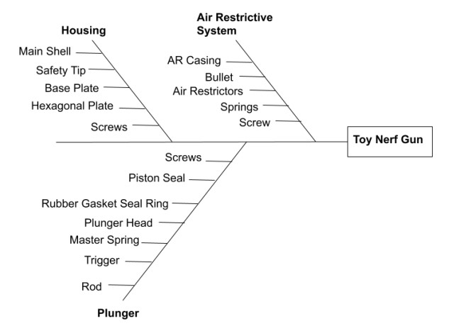
Next, we disassembled the nerf gun and produced a parts list of all of the individual components.
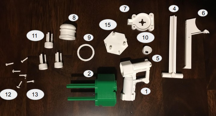
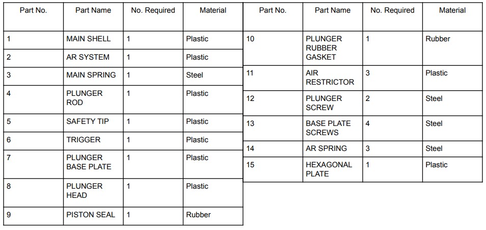
We then created sketches of the individual parts and subsystems.
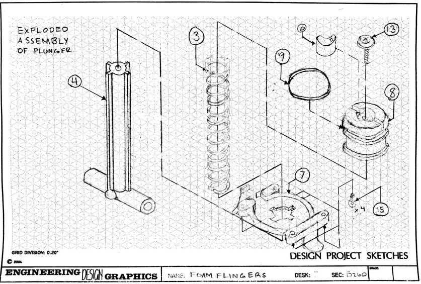
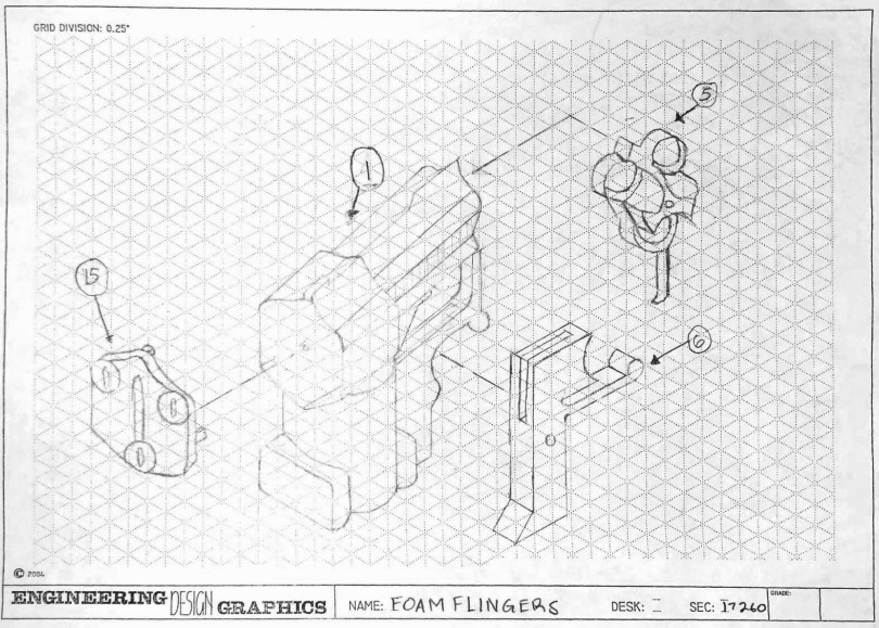
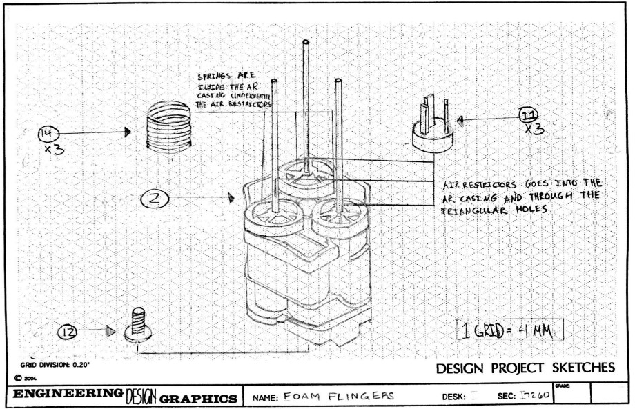
We also recreated all of the parts in SolidWorks and constructed an assembly.

An FEA analysis was also conducted to determine the stress a certain component would experience under a certain load. In our case, we chose the trigger of the nerf gun as that is the main component the user interacts with.
Over the course of the project, we also produced reports detailing progress as well as reports detailing manufacturing processess that I unfortunately could not find. The project itself was an enjoyable experience throughout. From dissassembly to re-creating the product in SolidWorks, I enjoyed all aspects of the project. In addition, it was great learning experience to with a group for a semester long project. As seen in the SolidWorks section of this website, I remade the SolidWorks model years later.

